


X. ELECTRICAL SYSTEM INFORMATION
Page 57
1998-2006 Edition
All Jamestown pellet stoves or inserts are designed with operational safety in mind. The following electrical safety
devices are included with every stove:
1. Full System 10 amp Fast Acting Fuse Protection
2. Thermal or Impedance Protection on All Motors
3. High Temperature Limit Switch
4. Low Temperature Limit Switch
5. Exhaust Blower Motor Failure and Exhaust System Blockage Protection Vacuum Switch
Caution
Only certified or qualified service technicians should perform analytical, repair or modification work. No other
adjustments may be made to the control system except those specified in this section.
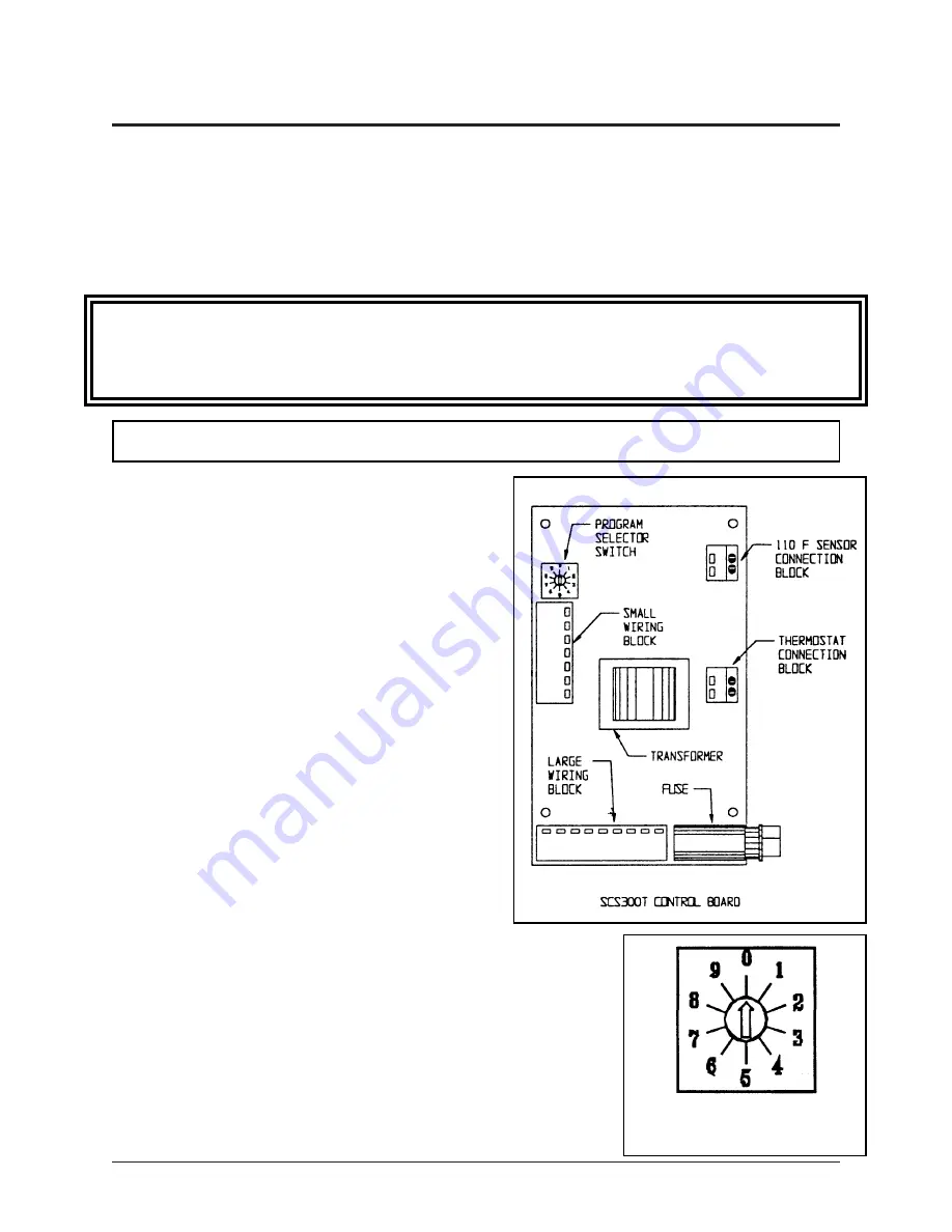
PROGRAM SELECTOR SWITCH
The SCS300T control board is a digitally programmed
control board designed solely for controlling Jamestown
pellet stoves. This control board employs a microprocessor
that drives the functions of the stove.
All four models of Jamestown pellet stoves [J1000B,
J2000T and J2001T and] will function identically. However,
each pellet stove model is programmed with its own unique
function parameters such as fuel feed rate, convection
blower speeds and automatic ignition cycle times. For your
safety, maximum and minimum fuel feed rates and
convection blower speeds are predetermined and
programmed and are not adjustable except as specified in
this section.
Please refer to the diagram of the control board to the right.
Located above the Small Wiring Block is the Program
Selector Switch.
Please refer to the diagram of the Program Selector Switch to the right. The
program selector switch has ten different positions. The Selector Switch
positions are numbered 0, 1....9. The arrow tip points to the number of the
program that is selected. To change the position of the arrow tip (and to
change the program), use a NON-MAGNETIC flat screw driver that has a tip
that is no larger than 1/10 inch (2.5mm) to rotate the arrow. When the arrow
is pointing to a number, for example, "1", the control board runs a program
using parameters that are given in Row #1 in the Program Parameters Tables
given on page 56. The Row Number corresponds to the position of the arrow
tip on the Program Selector Switch.
INTRODUCTION TO THE SCS300T CONTROL BOARD
Содержание J1000B
Страница 2: ......
Страница 8: ...Page vi 1998 2006 Edition ...
Страница 16: ...Page 8 1998 2006 Edition ...
Страница 20: ...Page 12 1998 2006 Edition ...
Страница 36: ...Page 28 1998 2006 Edition ...
Страница 38: ...Inside the Room and Recessed in an Interior Chase Page 30 1998 2006 Edition Recessed in an Exterior Chase ...
Страница 39: ...Corner Installation Page 31 1998 2006 Edition Installation requires standoffs to maintain clearances ...
Страница 44: ...Page 36 1998 2006 Edition ...
Страница 45: ...Page 37 1998 2006 Edition ...
Страница 46: ...VIII 5 Jamestown Control Panel Page 38 1998 2006 Edition ...
Страница 61: ...Page 53 1998 2006 Edition ...
Страница 62: ...Page 54 1998 2006 Edition ...
Страница 63: ...Page 55 1998 2006 Edition ...
Страница 64: ...Page 56 1998 2006 Edition ...
Страница 69: ...Page 61 1998 2006 Edition ...
Страница 70: ...Page 62 1998 2006 Edition ...
Страница 79: ...Appendix A 3 1998 2006 Edition ...
Страница 80: ...Appendix A 4 1998 2006 Edition ...
Страница 81: ...Appendix A 5 1998 2006 Edition ...
Страница 82: ...Appendix A 6 1998 2006 Edition ...
Страница 84: ...Appendix B 2 1998 2006 Edition ...
Страница 86: ...APPENDIX D EXHAUST BLOWER ASSEMBLY MODEL J1000 Appendix D 1 1998 2006 Edition Complete Assembly is Part 07DAA ...
Страница 87: ...APPENDIX E AUGER MOTOR BRACKET INSTALLATION Appendix E 1 1998 2006 Edition ...
Страница 90: ...Appendix F 3 1998 2006 Edition ...
Страница 93: ...APPENDIX H J1000 CROSSFLOW FAN Part 07EEG Appendix H 1 1998 2006 Edition ...
Страница 94: ...APPENDIX I 1 EXHAUST BLOWER ASSEMBLY MODEL J1000 Appendix I 1 1998 2006 Edition ...
Страница 96: ...SERVICE RECORD DATE SERVICED BY DESCRIPTION ...


