

VII. INSTRUCTIONS FOR FRAMING THE
J2001T OR J1001B FIREPLACE INSERT
Page 29
1998-2006 Edition
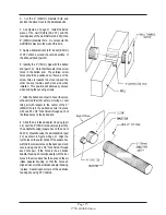
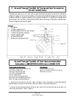
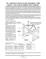
In planning the installation for the J2001T Insert, it is necessary to install certain components before the
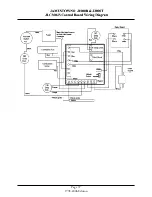
fireplace is completely positioned and installed. These include the direct vent system and the electrical wiring.
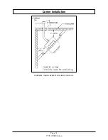
Determine if the fireplace is to be installed inside the room, recessed in the wall, corner mounted or elevated
on a hearth pad. The J2001T Fireplace Insert can be installed with a standard size shroud (part # C187) or
a large size shroud (part # C188). The opening in the framing for the fireplace is dependent on the shroud
that you choose and are listed in the table below. Both the standard and the large shroud will give the fireplace
proper clearance for the exhaust venting.
Positioning of the fireplace will vary depending on such factors as which shroud is being used and the amount
of wall, fascia or trim you want exposed. Place the Insert, with shroud, at the position that is desirable. Check
to make sure that this position serves form and function. Finalize the fireplace location.
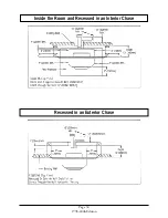
Determine the exact position of the fireplace so that the direct vent pipe is centered, if possible, between two
studs. This will avoid any extra framing. The back of the fireplace may be positioned 1" (25mm) clearance
from the combustible wall.
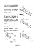
The height of the hearth is
optional.
However, 12-14
inches (305-356mm) is a good
height if you want to sit on the
hearth.
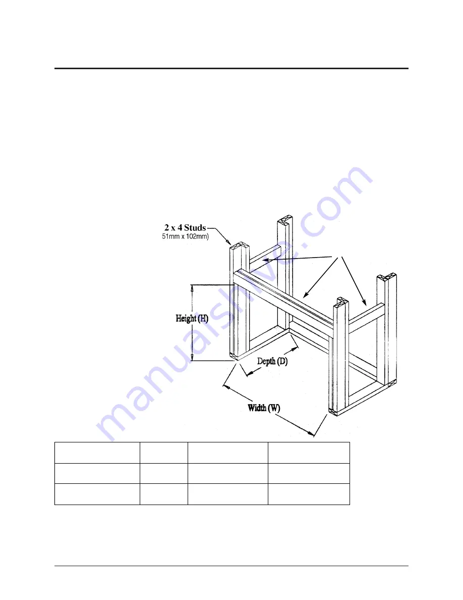
The fireplace framing should be
constructed of 2 x 4 (51mm x
102mm) lumber or heavier. To
install the fireplace recessed in
the wall, it is necessary to cut a
hole in the wall and build a
small insulated chase. A chase
is a box like structure built to
enclose the fireplace.
Caution: These instructions are
not substitutes for the
requirements of local building
codes. Therefore, your local
building codes must be
checked to determine the
requirements of these steps.
Chase Frame Opening Size
SHROUD SIZE
MIN / MAX
WIDTH (W)
INCHES (Millimeters)
HEIGHT (H)
INCHES (Millimeters)
C187 - 29" H x 41.5" W
(737mm H x 1054mm W)
MINIMUM
MAXIMUM
39.00" (991mm)
41.00" (1041mm)
27.50" (699mm)
28.00" (711mm)
C188 - 35" H x 49.5" W
(889mm H x 1257mm W)
MINIMUM
MAXIMUM
46.50" (1181mm)
48.25" (1226mm)
33.50" (851mm)
34.00" (864mm)
NOTE: These openings are measured from the top of the hearth pad.
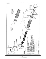
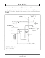
Depth of the Frame (D): The minimum depth (D) of the framing is 13" (330mm) for a Direct Through-the-Wall
vent system and 22" (559mm) for a Vertical vent system.
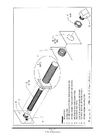
Height, Width and Depth standoffs
required when installing an insert
under new construction.
Содержание J1000B
Страница 2: ......
Страница 8: ...Page vi 1998 2006 Edition ...
Страница 16: ...Page 8 1998 2006 Edition ...
Страница 20: ...Page 12 1998 2006 Edition ...
Страница 36: ...Page 28 1998 2006 Edition ...
Страница 38: ...Inside the Room and Recessed in an Interior Chase Page 30 1998 2006 Edition Recessed in an Exterior Chase ...
Страница 39: ...Corner Installation Page 31 1998 2006 Edition Installation requires standoffs to maintain clearances ...
Страница 44: ...Page 36 1998 2006 Edition ...
Страница 45: ...Page 37 1998 2006 Edition ...
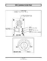
Страница 46: ...VIII 5 Jamestown Control Panel Page 38 1998 2006 Edition ...
Страница 61: ...Page 53 1998 2006 Edition ...
Страница 62: ...Page 54 1998 2006 Edition ...
Страница 63: ...Page 55 1998 2006 Edition ...
Страница 64: ...Page 56 1998 2006 Edition ...
Страница 69: ...Page 61 1998 2006 Edition ...
Страница 70: ...Page 62 1998 2006 Edition ...
Страница 79: ...Appendix A 3 1998 2006 Edition ...
Страница 80: ...Appendix A 4 1998 2006 Edition ...
Страница 81: ...Appendix A 5 1998 2006 Edition ...
Страница 82: ...Appendix A 6 1998 2006 Edition ...
Страница 84: ...Appendix B 2 1998 2006 Edition ...
Страница 86: ...APPENDIX D EXHAUST BLOWER ASSEMBLY MODEL J1000 Appendix D 1 1998 2006 Edition Complete Assembly is Part 07DAA ...
Страница 87: ...APPENDIX E AUGER MOTOR BRACKET INSTALLATION Appendix E 1 1998 2006 Edition ...
Страница 90: ...Appendix F 3 1998 2006 Edition ...
Страница 93: ...APPENDIX H J1000 CROSSFLOW FAN Part 07EEG Appendix H 1 1998 2006 Edition ...
Страница 94: ...APPENDIX I 1 EXHAUST BLOWER ASSEMBLY MODEL J1000 Appendix I 1 1998 2006 Edition ...
Страница 96: ...SERVICE RECORD DATE SERVICED BY DESCRIPTION ...