


Warning
V. GENERAL VENT SYSTEM INFORMATION
Page 11
1998-2006 Edition
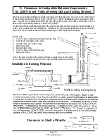
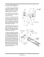
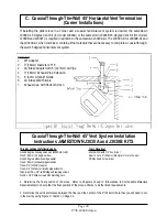
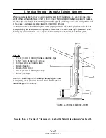
Using an Existing Chimney to Vent a Pellet Stove
Installations Requiring A Complete New Chimney System
When using an existing chimney to install the vent system for this pellet stove, be sure to line the entire length
of the chimney with three (3) inch or four (4) inch (76mm or 102mm) listed galvanized or stainless steel flexible
pipe if the chimney has a prior history of bad draft or if the chimney exceeds eleven (11) feet (3.4m) in height.
1. All complete new chimney systems must use listed L-type pellet vent pipe for all components of the vent
system. Use three (3) inch (76mm) diameter pipe when the total chimney length is under eleven (11) feet (3.4m)
and four (4) inch (102mm) diameter pipe when the total chimney length is over eleven (11) feet (3.4m).
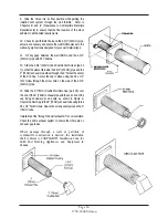
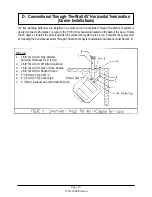
2. The exit terminal must be located not less than 60" (1.5m) from any opening through which combustion
products could enter the building (i.e. doors, windows, vents), nor less than 24" (610mm) to an adjacent
building and not less than 7" (178mm) above grade when located adjacent to public walkways. It must be
so arranged that flue gases are not directed so as to jeopardize people, overheat combustible structures, or enter
a building.
3. For horizontal venting, the exhaust pipe must be terminated by employing a listed end cap or 45 degree
elbow with a rodent screen cap that prevents rain or wind from entering the exhaust pipe. For termination
above the roof line, a listed rain cap must be used.
4. Each "L" Type joint must be completely sealed using High Temperature Silicone ("RTV"), three sheet
metal screws, and High Temperature Foil Tape.
Only use vent components that are listed for a National product safety certification agency. All venting components
used must be listed “PL” Vent or in existing chimney lined with listed solid fuel burning chimney lines (UL1482 and
ASTM E 1509 standards). Use of inferior components can lead to fire and carbon monoxide hazards and will void
all applicable warranty and any claims made towards the manufacturer.
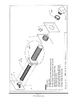
1. All existing chimneys larger than TEN (10) inches (254mm) in diameter or exceeding eleven (11) feet (3.4m) in
total length must be relined through their entire lengths using either a three (3) inch or four (4) inch (76mm or
102mm) stainless steel or galvanized flex pipe with a spark arrester/rain cap at the termination point.
2. Any chimney exceeding eleven (11) feet (3.4m) in height must be relined using a four (4) inch (102mm)
stainless steel or galvanized flex pipe with a spark arrestor/rain cap at the termination point.
3. Maximum vertical vent system length is 35 feet (10.7m). Maximum horizontal vent system length is 10
feet (3m).
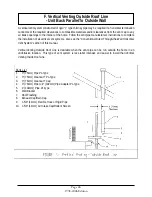
4. When using listed "L" type vent pipes and components, allow a minimum of twelve (12) inches (305mm)
between the exhaust termination and the outside air intake tube termination. Failure to maintain the required 12"
(305mm) separation may cause some exhaust gases to draw into the system resulting in an inefficient burn (lazy
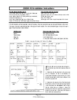
fire). When installing the Jamestown J3020A or the J3030B vent systems, however, it is not necessary to maintain
this 12" (305mm) distance between the exhaust termination and the outside air intake tube-termination. These
two vent kits have been tested and certified to be installed in variation to this 12" (305mm) separation requirement.
5. "L" Type pellet vent may be installed directly through a combustible wall, ceiling, or roof, using a listed wall
thimble, fire stop, or roof flashing. Clearance using a listed wall thimble will be a minimum of 1 1/2" (38mm) to any
combustible material; using a ceiling fire stop or roof flashing requires 3" (76mm) minimum clearance to any
combustible.
6. Check the spark arrestor or rain cap and ensure that the screens or louvers do not restrict exhaust flow.
7. Check the spark arrestor/rain cap on a regular basis to see if it is plugged with soot or flying debris such
as leaves.
Содержание J1000B
Страница 2: ......
Страница 8: ...Page vi 1998 2006 Edition ...
Страница 16: ...Page 8 1998 2006 Edition ...
Страница 20: ...Page 12 1998 2006 Edition ...
Страница 36: ...Page 28 1998 2006 Edition ...
Страница 38: ...Inside the Room and Recessed in an Interior Chase Page 30 1998 2006 Edition Recessed in an Exterior Chase ...
Страница 39: ...Corner Installation Page 31 1998 2006 Edition Installation requires standoffs to maintain clearances ...
Страница 44: ...Page 36 1998 2006 Edition ...
Страница 45: ...Page 37 1998 2006 Edition ...
Страница 46: ...VIII 5 Jamestown Control Panel Page 38 1998 2006 Edition ...
Страница 61: ...Page 53 1998 2006 Edition ...
Страница 62: ...Page 54 1998 2006 Edition ...
Страница 63: ...Page 55 1998 2006 Edition ...
Страница 64: ...Page 56 1998 2006 Edition ...
Страница 69: ...Page 61 1998 2006 Edition ...
Страница 70: ...Page 62 1998 2006 Edition ...
Страница 79: ...Appendix A 3 1998 2006 Edition ...
Страница 80: ...Appendix A 4 1998 2006 Edition ...
Страница 81: ...Appendix A 5 1998 2006 Edition ...
Страница 82: ...Appendix A 6 1998 2006 Edition ...
Страница 84: ...Appendix B 2 1998 2006 Edition ...
Страница 86: ...APPENDIX D EXHAUST BLOWER ASSEMBLY MODEL J1000 Appendix D 1 1998 2006 Edition Complete Assembly is Part 07DAA ...
Страница 87: ...APPENDIX E AUGER MOTOR BRACKET INSTALLATION Appendix E 1 1998 2006 Edition ...
Страница 90: ...Appendix F 3 1998 2006 Edition ...
Страница 93: ...APPENDIX H J1000 CROSSFLOW FAN Part 07EEG Appendix H 1 1998 2006 Edition ...
Страница 94: ...APPENDIX I 1 EXHAUST BLOWER ASSEMBLY MODEL J1000 Appendix I 1 1998 2006 Edition ...
Страница 96: ...SERVICE RECORD DATE SERVICED BY DESCRIPTION ...


