


Page 16
1998-2006 Edition
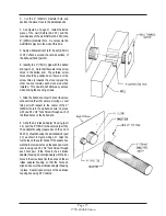
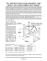
9. Slide the Stove into its final position while guiding the
installed vent system through the wall thimble. Refer to
Chapters III and IV (Clearances to Combustible Materials
Requirements) to ensure that the final position of the stove
adheres to all the listed requirements.
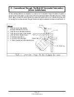
10. Check for wall thimble fit around the 4-3/4" (121mm) pipe,
adjust as necessary and secure the wall thimble pieces to the
wall using eight screws designed for your wall material type.
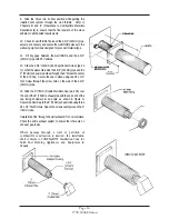
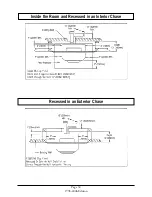
11. Fill any gaps between the wall thimble and the 4-3/4"
(121mm) pipe with RTV silicone.
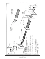
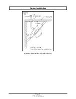
12. Slide the 4-3/4" (121mm) End Cap/Rodent Screen (part #
7) so that the sleeve fits inside the 4-3/4" (121mm) pipe and the
3" (76mm) exhaust pipe slides through the 3" hole at the center
of the End Cap. Secure the cap in place using one #8 x 1/2"
Teck Screw through the screw hole on the side of the 4-3/4"
(121mm) pipe.
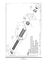
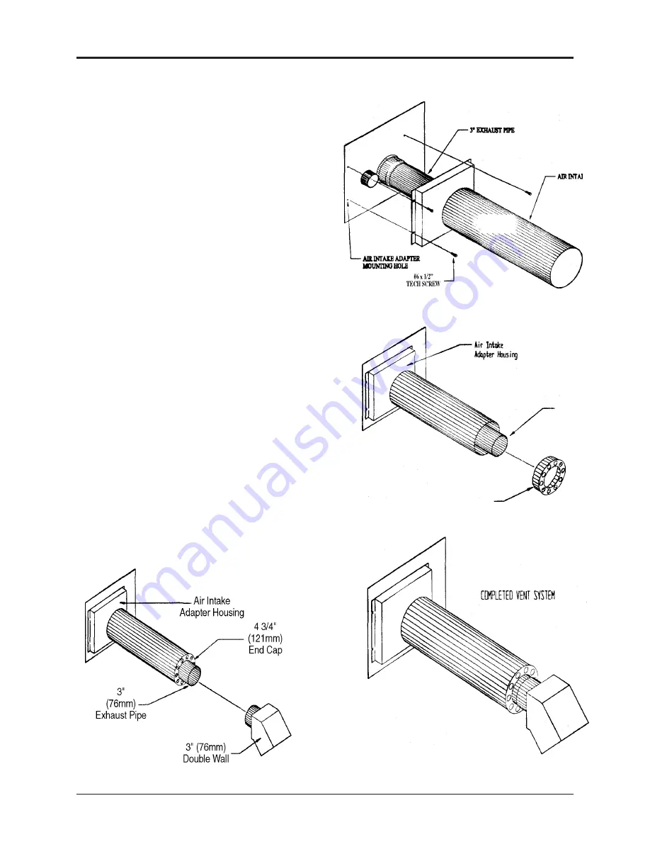
13. Slide the 3" (76mm) Double Wall Rain Cap ( part # 8) over
the end of the 3" (76mm) exhaust pipe with the open end of the
cap facing downward at an angle, as shown in Figure A.
Secure the Rain Cap to the 3" (76mm) exhaust tube using three
#8 x 1/2" Teck Screws. Space the screws evenly around the 3"
(76mm) tube.
Installation of the "through the wall exhaust kit" is now complete.
Check the entire exhaust system to ensure that there are no
exhaust gas leaks.
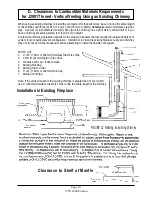
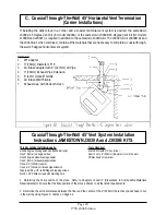
Where passage through a wall, or partition of
combustible construction is desired, the installation
shall conform to CAN/CSA-B365 Installation Code for
Solid Fuel Burning Appliances and Equipment in
Canada.
Содержание J1000B
Страница 2: ......
Страница 8: ...Page vi 1998 2006 Edition ...
Страница 16: ...Page 8 1998 2006 Edition ...
Страница 20: ...Page 12 1998 2006 Edition ...
Страница 36: ...Page 28 1998 2006 Edition ...
Страница 38: ...Inside the Room and Recessed in an Interior Chase Page 30 1998 2006 Edition Recessed in an Exterior Chase ...
Страница 39: ...Corner Installation Page 31 1998 2006 Edition Installation requires standoffs to maintain clearances ...
Страница 44: ...Page 36 1998 2006 Edition ...
Страница 45: ...Page 37 1998 2006 Edition ...
Страница 46: ...VIII 5 Jamestown Control Panel Page 38 1998 2006 Edition ...
Страница 61: ...Page 53 1998 2006 Edition ...
Страница 62: ...Page 54 1998 2006 Edition ...
Страница 63: ...Page 55 1998 2006 Edition ...
Страница 64: ...Page 56 1998 2006 Edition ...
Страница 69: ...Page 61 1998 2006 Edition ...
Страница 70: ...Page 62 1998 2006 Edition ...
Страница 79: ...Appendix A 3 1998 2006 Edition ...
Страница 80: ...Appendix A 4 1998 2006 Edition ...
Страница 81: ...Appendix A 5 1998 2006 Edition ...
Страница 82: ...Appendix A 6 1998 2006 Edition ...
Страница 84: ...Appendix B 2 1998 2006 Edition ...
Страница 86: ...APPENDIX D EXHAUST BLOWER ASSEMBLY MODEL J1000 Appendix D 1 1998 2006 Edition Complete Assembly is Part 07DAA ...
Страница 87: ...APPENDIX E AUGER MOTOR BRACKET INSTALLATION Appendix E 1 1998 2006 Edition ...
Страница 90: ...Appendix F 3 1998 2006 Edition ...
Страница 93: ...APPENDIX H J1000 CROSSFLOW FAN Part 07EEG Appendix H 1 1998 2006 Edition ...
Страница 94: ...APPENDIX I 1 EXHAUST BLOWER ASSEMBLY MODEL J1000 Appendix I 1 1998 2006 Edition ...
Страница 96: ...SERVICE RECORD DATE SERVICED BY DESCRIPTION ...


