


Page 15
1998-2006 Edition
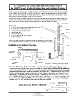
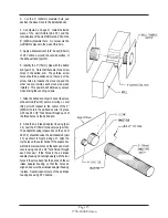
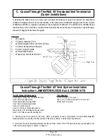
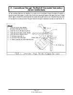
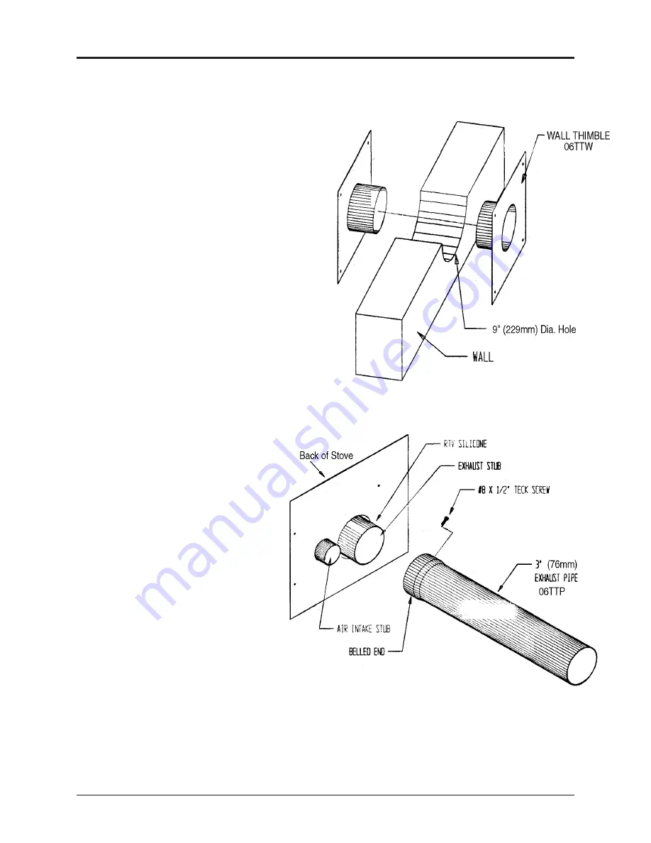
3. Cut the 9" (229mm) diameter hole and
position the stove close to the installation site.
4. See Figure A on page 17. Install the inside
piece of the wall thimble (Part #5) and the
outside piece of the wall thimble (Part #6) in the
9" (229mm) diameter hole. Do not secure the
wall thimble pieces to the wall at this time.
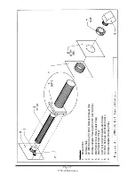
5. Apply a liberal amount (1/4" bead) (6.5mm)
of RTV silicone around the outside surface of
the Exhaust Stub (part #1).
6. Identify the 3" (76mm) pipe with the belled
end (part # 3). Note that there are three screw
holes in the belled end. These three screw
holes should be positioned so that one of the
screw holes is towards the stove top and the
other two are towards each stove side when
installed. This position will allow easy access
when driving the securing screws.
7. Slide the belled end of part #3 over the stove
exhaust stub (Part #1) as far as it will go. Level
this part with respect to the center of the 9"
(229mm) hole in the wall and secure it in place
with one #8 x 1/2" Teck Screw through each of
the three holes on the belled end.
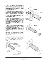
8. Slide the Air Intake Adapter Housing (part
# 4) over the 3" (76mm) exhaust pipe (part #3).
The adapter housing (square box on the end of
Part # 4) should envelop the air intake stub (part
# 2) as shown in Figure A Page 17. Align the
four holes on the outer bends of the square box
with the four screw holes on the back panel and
secure using one #8 x 1/2" Teck Screw through
each hole pair. If the holes in the air intake
adapter housing do not align easily with the four
holes in the stove back, flex the bends on the air
intake adapter housing so that the holes do
align and secure the air intake adapter housing
in place. Seal all open corners of the air intake
housing box using RTV silicone.
Содержание J1000B
Страница 2: ......
Страница 8: ...Page vi 1998 2006 Edition ...
Страница 16: ...Page 8 1998 2006 Edition ...
Страница 20: ...Page 12 1998 2006 Edition ...
Страница 36: ...Page 28 1998 2006 Edition ...
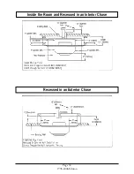
Страница 38: ...Inside the Room and Recessed in an Interior Chase Page 30 1998 2006 Edition Recessed in an Exterior Chase ...
Страница 39: ...Corner Installation Page 31 1998 2006 Edition Installation requires standoffs to maintain clearances ...
Страница 44: ...Page 36 1998 2006 Edition ...
Страница 45: ...Page 37 1998 2006 Edition ...
Страница 46: ...VIII 5 Jamestown Control Panel Page 38 1998 2006 Edition ...
Страница 61: ...Page 53 1998 2006 Edition ...
Страница 62: ...Page 54 1998 2006 Edition ...
Страница 63: ...Page 55 1998 2006 Edition ...
Страница 64: ...Page 56 1998 2006 Edition ...
Страница 69: ...Page 61 1998 2006 Edition ...
Страница 70: ...Page 62 1998 2006 Edition ...
Страница 79: ...Appendix A 3 1998 2006 Edition ...
Страница 80: ...Appendix A 4 1998 2006 Edition ...
Страница 81: ...Appendix A 5 1998 2006 Edition ...
Страница 82: ...Appendix A 6 1998 2006 Edition ...
Страница 84: ...Appendix B 2 1998 2006 Edition ...
Страница 86: ...APPENDIX D EXHAUST BLOWER ASSEMBLY MODEL J1000 Appendix D 1 1998 2006 Edition Complete Assembly is Part 07DAA ...
Страница 87: ...APPENDIX E AUGER MOTOR BRACKET INSTALLATION Appendix E 1 1998 2006 Edition ...
Страница 90: ...Appendix F 3 1998 2006 Edition ...
Страница 93: ...APPENDIX H J1000 CROSSFLOW FAN Part 07EEG Appendix H 1 1998 2006 Edition ...
Страница 94: ...APPENDIX I 1 EXHAUST BLOWER ASSEMBLY MODEL J1000 Appendix I 1 1998 2006 Edition ...
Страница 96: ...SERVICE RECORD DATE SERVICED BY DESCRIPTION ...


