background image

INSTALLER / CONSUMER

SAFETY INFORMATION

20002191  11/02  Rev. 10

PLEASE READ THIS MANUAL
BEFORE INSTALLING AND USING
APPLIANCE.

WARNING!

IF THE INFORMATION IN THIS
MANUAL IS NOT FOLLOWED
EXACTLY, A FIRE OR EXPLOSION
MAY RESULT CAUSING PROP-
ERTY DAMAGE, PERSONAL IN-
JURY OR LOSS OF LIFE.

FOR YOUR SAFETY

Installation and service must be per-
formed by a qualified installer, service
agency or the gas suppler.

WHAT TO DO IF YOU SMELL GAS:

Do not try to light any appliance.

Do not touch any electric switch; do
not use any phone in your building.

Immediately call your gas supplier
form your neighbor’s phone. Follow
the gas supplier’s instructions.

If you cannot reach your gas supplier,
call the fire department.

DO NOT STORE OR USE GASO-
LINE OR OTHER FLAMMABLE
VAPORS AND LIQUIDS IN THE
VICINITY OF THIS OR ANY OTHER
APPLIANCE.

This appliance may be installed in an after
market permanently located manufac-
tured (mobile) home where not prohibited
by local codes.

This appliance is only for use with the
type of gas indicated on the rating plate.

This appliance is not convertible for use
with other gases unless a certified kit is
used.

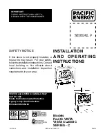
Jefferson

®

Direct Vent/Natural

Vent Gas Heater

Homeowner’s Installation

and Operation Manual

Tested and listed to

ANSI Z21.88b-2001 and CSA-2.33b-2001

INSTALLER: DO NOT DISCARD THIS MANUAL - LEAVE FOR HOMEOWNER

C E RT I F I E D

DESIGN

CER

TIFIE D

Model JDV:  2820, 2822, 2823,
2825, 2827, 2828

410 Admiral Blvd. • Mississauga, Ontario, Canada L5T 2N6 • 905-670-7777

www.majesticproducts.com • www.vermontcastings.com

Vermont Castings, Majestic Products

Содержание 820

Страница 1: ... call the fire department DO NOT STORE OR USE GASO LINE OR OTHER FLAMMABLE VAPORS AND LIQUIDS IN THE VICINITY OF THIS OR ANY OTHER APPLIANCE This appliance may be installed in an after market permanently located manufac tured mobile home where not prohibited by local codes This appliance is only for use with the type of gas indicated on the rating plate This appliance is not convertible for use wi...

Страница 2: ...tions Direct Vent ONLY 12 Assembly Procedures Tools Required 13 Unpack the Stove 13 Install Optional Fan 13 Venting System Assembly Direct Vent 14 Install Vent Adapter Pipe CFM Components 14 Install Vent Adapter Pipe Simpson Dura Vent Components 15 Side Wall Termination Assembly 16 Vent Termination Below Grade 17 Vertical Through the Roof Vent Assembly 18 Venting System Assembly Natural Vent 19 In...

Страница 3: ...or combus tion and vent the exhaust vertically through the roof to the atmosphere This appliance is approved for bedroom installations in the U S and Canada This appliance may be installed in an aftermarket manufactured mobile home where not prohibited by state or local codes WARNING Operation of this heater when not con nected to a properly installed and maintained venting system can result in ca...

Страница 4: ...ter is desired the Vermont Castings Z31D00 FSDHAG Draft Hood must be directly installed to the top of the unit according to the installation instructions The Draft Hood Adapter is available in the 7FSKHASK stove kit or as a separate item When the Jefferson stove is converted to Natural Vent it uses 4 vent pipe For aesthetic purposes the CFM direct vent system may be used up to the ceiling See Page...

Страница 5: ...location of outside walls Where additional heat is needed Where family members gather most often The vent system requirements NOTE We do not recommend the use of wallpaper next to this stove Over time radiant heat may cause the wallpaper to shrink or may adversely affect the binders in the wallpaper adhesive Clearance Requirements Minimum Clearances to Combustible Materials Measure side clearances...

Страница 6: ...h There are no other hearth require ments A Wall Thimble Centerline from Floor A Effective Minimum Wall Thimble 58 1480mm CFM Majestic Pipe Centerline 54 1378mm Simpson DuraVent Pipe ST131a Fig 5 Minimum wall thimble centerline Direct Vent Only Wall and Ceiling Clearances needed for installing DuraVent Minimum Vent Kit 2792 or CFM Majestic Minimum Vent Kit 7TFSDVSK A C D B A Rear Wall 4 102mm B Mi...

Страница 7: ... installation and operational procedures For assistance or additional information consult a qualified installer service agency or the gas supplier Gas Specifications Max Min Input Input Model Fuel Gas Control BTU h BTU h JDVRN Nat Millivolt 28 000 20 000 JDVRP Prop Millivolt 28 000 19 000 Natural LP Propane Inlet Minimum 5 5 w c 11 0 w c Inlet Maximum 14 0 w c 14 0 w c Manifold Pressure 3 5 w c 10...

Страница 8: ...n consider the location of the vent terminal and clearances Some of the most common clearances to keep in mind are shown in Figure 10 Important All vent clearances must be maintained Check your vent termination clearances against Figures 10 and 11 The vent should be placed so that people cannot be burned by accidentally touching the vent surfaces when the stove is operating The vent termination sh...

Страница 9: ...pt where stated otherwise Venting terminals shall not be recessed into a wall or siding Horizontal venting must be installed on a level plane without an inclining or declining slope There must not be any obstruction such as bushes garden sheds fences decks or utility buildings within 24 from the front of the termination hood Do not locate termination hood where excessive snow or ice build up may o...

Страница 10: ... Clearance to service regulator vent outlet 3 feet 91cm 3 feet 91cm J Clearance to nonmechanical air supply inlet 6 inches 15cm for appliances 10 000 6 inches 15cm for appliances to building or the combustion air inlet to any Btuh 3kW 12 inches 30cm for 10 000 Btuh 3kW 9 inches other appliances appliances 10 000 Btuh 3kW and 23cm for appliances 10 000 100 000 Btuh 30kW 36 inches 91cm Btuh 3kW and ...

Страница 11: ...16 14 12 10 8 16 18 20 22 24 26 28 30 32 34 36 4 6 8 10 12 14 A B Fig 11 Vent termination window Natural Vent ONLY FP567b NOTE When using the FSDHAG the restrictor plate supplied with the stove is not used Outside Corner Inside Corner Termination Clearances Termination clearances for buildings with combustible and noncombustible exteriors A Combustible 6 152mm Noncombustible 2 50mm B Combustible 6...

Страница 12: ...bow CG 1 24 Straight pipe CG 1 36 Straight pipe CG 1 Side Wall Termination 1 Firestop 1 Zero clearance sleeve 1 Hardware package 1 Finishing plate CG 1 Finishing collar CG 4 Polished Brass flue pipe rings Through the Wall Vent Kit 7TFSDVSK 1 90 Degree Elbow CG 1 24 Straight pipe CG 1 48 Straight pipe CG 1 Side Wall Termination 1 Firestop 1 Zero clearance sleeve 1 Hardware package 1 Finishing plate...

Страница 13: ...ter protected by a towel 4 Take the logset and all other loose parts out of the firebox and set them aside in a protected area for installation after the venting is complete NOTE Verify the two relief doors located on top of the firebox are properly seated on the gasket The doors should sit flush on the gasket and should lift easily from the seal around the opening Install the Optional Fan If you ...

Страница 14: ... the assembly with three sheet metal screws Fig 17 3 Dry fit the Inner pipe assembly to the stove and determine the required vent length Insert the vent assembly into the flue collar but do not attach Measure to determine the correct length required for your installation and cut the upper end of the pipe as necessary Dry fit the outer vent section and cut to match the height of the Inner assembly ...

Страница 15: ...starter with the next section of inner vent pipe Fig 18 Attach inner assembly to flue collar ST212 CEMENT ST213 Fig 19 Fasten outer pipe with 12 x 1 2 sheet metal screw Install the Vent Adapter Pipe Simpson Dura Vent Components 1 Install the Restrictor Plate Consult the Vent Run Specifications on page 8 to determine whether the restrictor plate is needed If so put the restrictor plate in place wit...

Страница 16: ...h the holes Fig 23 NOTE The wall sleeve is required in combustible walls only 3 Install the Wall Firestop Sleeve assembly into the wall cutout and fasten the firestop to the wall cutout framing members Fig 23 12 305mm Max Length Sleeve 8 Sheet Metal Screws Firestop ZCS103 Fig 23 Assemble the wall sleeve and firestop For DuraVent pipe only Install vent pipe by aligning the locking system together s...

Страница 17: ...pipe joints if desired Seal Both Terminal Ends Caulk Plate Joint with Weatherproof Sealant ST217 Fig 27 Install the vent terminal Vent Termination Below Grade Install Snorkel Kit 7FSDVSKS when it is not possible to meet the required vent termination clearances of 12 305mm above grade level The snorkel kit will allow installation depth of down to 7 178mm below grade level The seven inches is measur...

Страница 18: ...evel an attic insulation shield must be installed Recessed Wall Sheet Metal Screws and Bracket Wall Screws and Anchors Waterproof Seal Around Pipe ST219 Fig 29 Use extension brackets to mount snorkel against recessed wall Firestop Finishing Collar 7 Pipe Wall Plate Waterproof Seal Around Pipe Firestop Window Well Drain 4 Clearance Snorkel Termination Cap Wall Screws and Anchors ST218 Gravel Fig 28...

Страница 19: ... switch Fig 64 Page 33 Decorative 7 Pipe 4 B vent Pipe Draft Hood Adapter ST358 Fig 32 Decorative 7 pipe may be fitted around the B vent pipe CFM Direct Vent System may be used after Draft Hood up to the ceiling Operating the stove when it is not connected to a properly installed and maintained venting system or tampering with or disconnecting the vent safety switch can result in carbon monoxide C...

Страница 20: ...ns on the burner brackets Fig 34 4 Loosely sprinkle the lava rocks directly on top of the burner between the decorative grate and the middle logs Do not place any ember material behind the middle logs Fig 35 5 Engage the upper log with the rear log and the right middle log as shown in Figure 35 Engage the top log with the upper log and the left middle log Fig 35 4 5 1 3 2 CEMENT Fig 33 Install dra...

Страница 21: ...of 28 000 BTUs at a manifold pressure of 10 0 and minimum inlet supply for adjustment of 11 0 w c CAUTION Burner Information The appliance must only use the gas specified on the rating plate unless converted using a Vermont Cast ings Fuel Conversion Kit To convert from LP to Natural Gas use Kit 000 5021 To convert from Natural Gas to LP use Kit 000 5022 Conversion instructions are provided with ea...

Страница 22: ... a minimum 1 2 opening to fully open Fig 40 You may have to try more than once to find the correct air shutter opening for best results depending on your altitude 9 Refasten the two nuts and assemble the burner into the unit by sliding the burner in at an angle with the left side lower than the right side Slide the left side onto the injectors Lower the right hand side down into place Make sure th...

Страница 23: ...f stove under bottom of rear shroud to valve 3 Attach wires to valve terminals Fig 43 Switch Assembly Screws Existing Holes ST315 Fig 42 Attach switch assembly to rear shroud PILOT ADJ TP TH TPTH ST228 Fig 43 Attach switch wires to valve Install the Stove Front The Front Plate attaches to the stove by four steel tabs that engage with corresponding cast ribs on the sides and bottom of the stove bod...

Страница 24: ...ermostat rated for 500 millivolts Check the table below for the appropriate gauge thermostat wire to use for the length of lead required in your installation 1 Install the wall thermostat in the desired location and run the wires to the stove location Terminate these leads with 1 4 female connectors 2 Connect the thermostat wires to the valve Fig 43 This completes assembly of the Jefferson stove ...

Страница 25: ...act your dealer or a qualified gas technician for assistance Do not operate the heater until the pilot flame is correct Follow regular maintenance procedures as described on Page 30 Fig 46 Pilot Assembly location Thermocouple ST232 Pilot Assembly Flame Temperature Adjustment For stoves equipped with HI LO valves flame adjust ment is accomplished by rotating the HI LO adjustment knob located near t...

Страница 26: ...s exactly B BEFORE LIGHTING smell all around the heater area for gas Be sure to smell next to the floor because some gas is heavier than air and will settle on the floor WHAT TO DO IF YOU SMELL GAS Do not try to light any fireplace Do not touch any electric switch Do not use any phone in your building Immediately call your gas supplier from a neighbor s phone Follow the gas supplier s instructions...

Страница 27: ...The thermo couple operates the pilot flame Tighten the thermo couple The thermopile operates the main valve ON and OFF Clean and or adjust pilot for maximum flame impingement on thermocouple and thermopile Turn valve knob to Pilot Maintain flow to pilot millivolt meter should read greater than 10mV If the reading is okay and the pilot does not stay on replace the gas valve NOTE An interrupter bloc...

Страница 28: ...h the conversion P IL O T ON OFF PILOT ADJ L O H I Main Gas Line Gas Supply Inlet ST226 Fig 51 Attach the gas line to the left side of the valve Conversion Procedure 1 Remove stove front Lift stove front up and then swing bottom out and away to disengage from the stove body Fig 59 Page 31 2 Swing open the swiveling latches at the top left and right corners of the glass frame Fig 60 Page 31 3 Pull ...

Страница 29: ...rner Leg Injector Orifices ST353a Fig 58 Remove and replace injector orifices Table 2 Injector Orifice Size Matrix Conversion to Natural Gas Input BTU h Kit Front Part Rear Part Minimum Maxi mum 000 5021 54 055 20000130 44 086 30000334 19 000 28 000 Conversion to LP Input BTU h Kit Front Part Rear Part Minimum Maximum 000 5022 69 029 30000513 54 055 20000130 20 000 28 000 Pilot Hood Pilot Bracket ...

Страница 30: ...king new Use high temperature stove paints available through your local dealer to touch up areas as needed Clean areas to be painted with a wire brush and be sure to cover the logs burner and valve assembly glass and frame assembly Apply the paint sparingly two light coats of paint will give better results than a single heavy coat Clean porcelain enamel surfaces with a soft damp cloth Do not use a...

Страница 31: ...ting properly check the flames periodically to confirm that they match Figure 62 The flames will be blue during the first 15 20 minutes of operation and will gradually turn to yellow after that Do not use your stove if the flame pattern differs from that shown here Contact your Vermont Castings dealer or a qualified technician for help Inspect the Vent System Annually Have the vent system inspecte...

Страница 32: ... Thermostat Wiring On Off Switch Wiring ST124b OFF ON Thermopile Black Black TP TH TP TH Thermostat Optional Thermopile Black Black TP TH TP TH FAN JUNCTION BOX FAN POWER CORD Strain Relief Chassis Ground BLK GRN GRN WHT ON OFF Rheostat Chassis Ground RHEOSTAT SNAPSTAT BOX Snapstat BLK B L K BLK BLK BLK WHT MOTOR SNAPSTAT ON OFF RHEOSTAT WHT WHT BLK BLK BLK GRN BLK Schematic Diagram ST234 ST153 Fi...

Страница 33: ... design materials specifications prices and discontinue colors and products at any time without notice 2191 Jefferson Direct Vent Natural Vent Gas Heater Models 2820 2822 2823 2825 2827 2828 Ref Description JDV 1 Gas Log Set JDV 20002182 1a Log Back JDV 20002183 1b Log Left Upper JDV 20002187 1c Log Right Upper JDV 20002186 1d Log Left JDV 20002185 1e Log Right JDV 20002184 2 Grille JDV 30000685 3...

Страница 34: ...sing Assembly NG LP 20002214 19 Grate Burner JDV 20002167 20 Wiring Harness FSDV32RN JDV 10002582 21 Switch ON OFF RN RP Models 30000874 22 Front JDV Refer to Enamel Parts Chart Page 34 23 Door Control JDV 30000686 24a Orifice Hood 69 Front LP 30000513 24b Orifice Hood 54 Front NG 20000130 24c Orifice Hood 54 Rear LP 20000130 24d Orifice Hood 44 Rear NG 30000334 25 Bracket Right Log JDV 20002166 2...

Страница 35: ...ntenance however periodic cleaning of the fan and the surrounding area is required Installation Refer to Page 13 for installation instructions Remote Controls The remote control allows you to turn the heater on or off from anywhere in the room Refer to Page 40 for wiring diagrams Model Functions Controlled MRC1 ON OFF MRC2 ON OFF and Temperature MRC3 ON OFF and Temperature control with a digital d...

Страница 36: ...ction the damage is found to be the fault of the manufacturer repairs will be authorized at no charge to the customer parts and or labor Any part and or component replaced under the provisions of this warranty is covered for six months or the remainder of the original warranty whichever is longest This warranty is limited to the repair of or replacement of part s found to be defective in material ...

Отзывы: