


VIII.9 STARTING A FIRE FOR THE FIRST TIME
Manual Mode
Page 45
1998-2006 Edition
The control system in the stove is set to manual mode if either a wall switch is installed or if a wall thermostat is
connected and is fixed in the ON position.
1. Read and follow instructions (1) through (4) given in Automatic and Semiautomatic Modes - STARTING A FIRE
FOR THE FIRST TIME, on page 41.
2. Turn the Fuel Feed Control Knob clockwise to a setting of "6".
3. Turn the Draft Control Knob to "3" and push the Main Power ON/OFF Switch to the "ON" position.The green
POWER ON indicator light will illuminate.
4. Turn the Wall Switch to the ON position. The orange IGNITOR ON indicator light will illuminate and the red FUEL
ON indicator light will flash on and off. Since the fuel feed auger system is most likely empty, it may take up to 7
minutes before you see any pellets dropping into the firepot. NOTE: The only time you need to "prime" the auger
with fuel is when the stove has run out of fuel or when you are starting the stove for the very first time. When you
see pellets start to drop into the firepot, turn the wall thermostat to the "OFF" position and wait for 5 minutes.
5. After 5 minutes, turn the Main Power switch OFF then ON. The 12 minute startup cycle will begin. The orange
IGNITOR ON indicator light will illuminate and the red FUEL ON indicator light will flash on and off. Pellets will start
to drop into the firepot. Verify the fuel feed rate by counting the number of seconds the red FUEL ON indicator light
stays ON and also the number of seconds it stays OFF.
6. The orange IGNITOR ON indicator light will remain lit for 5 minutes. The pellets in the firepot must ignite and flame
up within these 5 minutes. If a flame is present before the end of the 5 minutes, let the stove continue running without
changing any of the controls. If a flame is not present at the end of the 5 minutes, turn the Wall Switch to the OFF
position, empty the pellets from the firepot into a non-combustible metal container and check the firepot for proper
placement and alignment. See Page 51 of this manual. Reposition and realign the firepot. Repeat Steps 4 and 5.
Warning
A few glowing embers may be present in the firepot. Never empty the contents of the firepot into the fuel hopper
or any other combustible container.
NOTE
If the stove does not warm up sufficiently by the
end of the 12 minute startup cycle, the red Fuel
ON indicator light will turn OFF and the green
Power ON indicator light will flash once every
two seconds indicating that the stove did not
warm up sufficiently. If this occurs, turn the
main power switch to OFF then back to ON.
This will reinitiate the 12 minute startup cycle.
If this problem persists, see Section X on how
to adjust the control board to increase the fuel
feed rate during the startup cycle.
7. If the stove warms up sufficiently during the 12 minute startup
cycle, the convection blower should increase in speed. Similarly,
at the end of the 12 minute startup cycle, the Fuel ON indicator
light should begin to stay ON for longer periods and stay OFF
for shorter periods. An increased amount of fuel should begin
to feed into the firepot.
8. Let the stove burn at this rate for 5 minutes. After 5 minutes,
adjust the Feed Rate Control Knob to the desired position, wait
2 minutes then adjust the Draft Control Knob accordingly for an
efficient burn. During the first hour of burn, check for proper air
to fuel ratio and efficient flame characteristics and adjust the
Draft Control Knob if necessary. If you plan to leave the Fuel
Feed Control Knob at one fixed position for all future burn
sessions, it is not necessary to adjust the Draft Control Knob again. However, any time you adjust the Fuel Feed
Rate Control Knob position, you must adjust the Draft Control Knob position to achieve an efficient flame
characteristic.
If you encounter any difficulties achieving a flame within the first 5 minutes or establishing an efficient flame pattern,
please consult the Trouble Shooting Guide in this manual. If you are unable to remedy the problem, please contact
your local Jamestown Dealer.
Содержание J1000B
Страница 2: ......
Страница 8: ...Page vi 1998 2006 Edition ...
Страница 16: ...Page 8 1998 2006 Edition ...
Страница 20: ...Page 12 1998 2006 Edition ...
Страница 36: ...Page 28 1998 2006 Edition ...
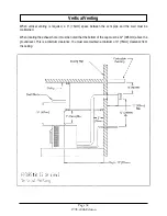
Страница 38: ...Inside the Room and Recessed in an Interior Chase Page 30 1998 2006 Edition Recessed in an Exterior Chase ...
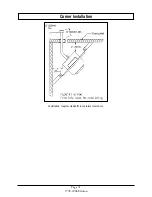
Страница 39: ...Corner Installation Page 31 1998 2006 Edition Installation requires standoffs to maintain clearances ...
Страница 44: ...Page 36 1998 2006 Edition ...
Страница 45: ...Page 37 1998 2006 Edition ...
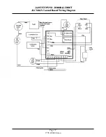
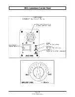
Страница 46: ...VIII 5 Jamestown Control Panel Page 38 1998 2006 Edition ...
Страница 61: ...Page 53 1998 2006 Edition ...
Страница 62: ...Page 54 1998 2006 Edition ...
Страница 63: ...Page 55 1998 2006 Edition ...
Страница 64: ...Page 56 1998 2006 Edition ...
Страница 69: ...Page 61 1998 2006 Edition ...
Страница 70: ...Page 62 1998 2006 Edition ...
Страница 79: ...Appendix A 3 1998 2006 Edition ...
Страница 80: ...Appendix A 4 1998 2006 Edition ...
Страница 81: ...Appendix A 5 1998 2006 Edition ...
Страница 82: ...Appendix A 6 1998 2006 Edition ...
Страница 84: ...Appendix B 2 1998 2006 Edition ...
Страница 86: ...APPENDIX D EXHAUST BLOWER ASSEMBLY MODEL J1000 Appendix D 1 1998 2006 Edition Complete Assembly is Part 07DAA ...
Страница 87: ...APPENDIX E AUGER MOTOR BRACKET INSTALLATION Appendix E 1 1998 2006 Edition ...
Страница 90: ...Appendix F 3 1998 2006 Edition ...
Страница 93: ...APPENDIX H J1000 CROSSFLOW FAN Part 07EEG Appendix H 1 1998 2006 Edition ...
Страница 94: ...APPENDIX I 1 EXHAUST BLOWER ASSEMBLY MODEL J1000 Appendix I 1 1998 2006 Edition ...
Страница 96: ...SERVICE RECORD DATE SERVICED BY DESCRIPTION ...


