


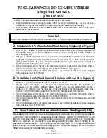


J3020A Kit Installation Instructions
Page 14
1998-2006 Edition
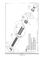
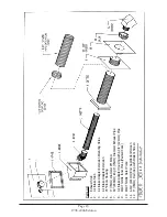
This kit contains the following parts:
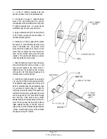
One Air intake adapter housing w/ 4-3/4” (121mm) air Intake pipe
One 4-3/4” (121mm) End Cap/ Rodent Screen
One 19” (483mm) length of 3” (76mm) exhaust pipe w/belled end
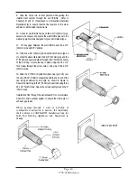
One Wall Thimble (2 pieces)
One 3” (76mm) Double Wall Rain Cap w/ Rodent Screen
Sixteen 1/2” #8 Hex Head self drilling & tapping Screws (Teck Screw)
Tools and other materials required:
Hand Drill with 1/4” Hex Driver
Appropriate Saw(s) to Cut 9” (229mm) Diameter Hole in Wall
Phillips Head Screw Driver
Power Drill, Phillips bit
Caulking gun with a tube of High Temperature RTV silicone
Wall Material
Wood
Sheet Metal
Masonry
Dry Wall
Recommended Screw Type
3/4” #6 Wood Screw
1/2” #6 Sheet Metal Screw
1-1/2” Molly Bolts
1” #6 sheet metal screws with plastic anchors
This kit contains all the materials, except 8 screws, that are needed to secure the wall thimble to the wall.
The type of screws needed depends on the type of wall material. The recommended type of screw for each
type of wall material is listed below:
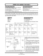
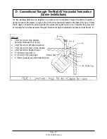
TABLE 1: Location Of Center Of 9" Hole In The
Wall
MODEL
J1000B w/
J1000B w/
J1000B
J2000T
J2000T
J2001T
Sheet Metal
Legs
Cast Legs
w/ Pedestal
W/ Pedestal w/ Cast Legs
LEFT
From
Center
Line
1/8"
(3mm)
1/8"
(3mm)
1/8"
(3mm)
1-5/8"
(41mm)
1-5/8"
(41mm)
1-5/8"
(41mm)
UP From
Floor Board
8-3/4" (222mm)
[add 1-3/4"
(45mm) if leg
balls are used]
10-1/2"
(267mm)
8-7/8"
(225mm)
13-1/2"
(343mm)
11-7/8"
(302mm)
4-1/2" (114mm)
[if using a riser add
riser height]
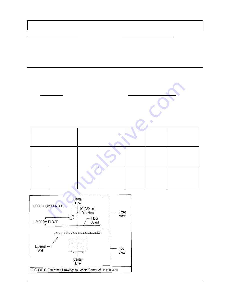
LEFT: Left of the center line as shown in Figure X.
UP: Up from the top of the floor board as shown in
Figure X.
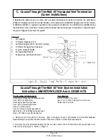
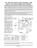
1. Determine the final position for the stove and
refer to Chapters III and IV (Clearances to
Combustible Materials Requirements) to ensure
that the final position of the stove adheres to all
the listed requirements.
2. Determine the center of the 9" (229mm) hole
that needs to be cut in the wall by using Figures
X and the table above. Example: J1000 w/ Legs.
find the center line as in Figure 2. Move 1/8"
(3mm) to the left of the center line and up 8-3/4"
(222mm) from the floor. This point is the center of
the 9" (229mm) diameter hole.
Содержание J1000B
Страница 2: ......
Страница 8: ...Page vi 1998 2006 Edition ...
Страница 16: ...Page 8 1998 2006 Edition ...
Страница 20: ...Page 12 1998 2006 Edition ...
Страница 36: ...Page 28 1998 2006 Edition ...
Страница 38: ...Inside the Room and Recessed in an Interior Chase Page 30 1998 2006 Edition Recessed in an Exterior Chase ...
Страница 39: ...Corner Installation Page 31 1998 2006 Edition Installation requires standoffs to maintain clearances ...
Страница 44: ...Page 36 1998 2006 Edition ...
Страница 45: ...Page 37 1998 2006 Edition ...
Страница 46: ...VIII 5 Jamestown Control Panel Page 38 1998 2006 Edition ...
Страница 61: ...Page 53 1998 2006 Edition ...
Страница 62: ...Page 54 1998 2006 Edition ...
Страница 63: ...Page 55 1998 2006 Edition ...
Страница 64: ...Page 56 1998 2006 Edition ...
Страница 69: ...Page 61 1998 2006 Edition ...
Страница 70: ...Page 62 1998 2006 Edition ...
Страница 79: ...Appendix A 3 1998 2006 Edition ...
Страница 80: ...Appendix A 4 1998 2006 Edition ...
Страница 81: ...Appendix A 5 1998 2006 Edition ...
Страница 82: ...Appendix A 6 1998 2006 Edition ...
Страница 84: ...Appendix B 2 1998 2006 Edition ...
Страница 86: ...APPENDIX D EXHAUST BLOWER ASSEMBLY MODEL J1000 Appendix D 1 1998 2006 Edition Complete Assembly is Part 07DAA ...
Страница 87: ...APPENDIX E AUGER MOTOR BRACKET INSTALLATION Appendix E 1 1998 2006 Edition ...
Страница 90: ...Appendix F 3 1998 2006 Edition ...
Страница 93: ...APPENDIX H J1000 CROSSFLOW FAN Part 07EEG Appendix H 1 1998 2006 Edition ...
Страница 94: ...APPENDIX I 1 EXHAUST BLOWER ASSEMBLY MODEL J1000 Appendix I 1 1998 2006 Edition ...
Страница 96: ...SERVICE RECORD DATE SERVICED BY DESCRIPTION ...


