


Appendix B-1
1998-2006 Edition
APPENDIX B
CAST LEGS J2067T AND GOLD LEGS
J2068T KITS FOR APPLIANCE MODELS
J1000B and J2000T
Parts List
1. Four Cast Legs (Black or Gold)
2. Eight 1/4" x 1" (20nc) Bolts
3. Eight Lock Washers
Tools Required
1. Adjustable Wrench
2. Phillips Screw Driver
1. After having removed the packaging material from around the appliance, tip the unit on its back and lay it
gently on a non-abrasive surface such as carpeting.
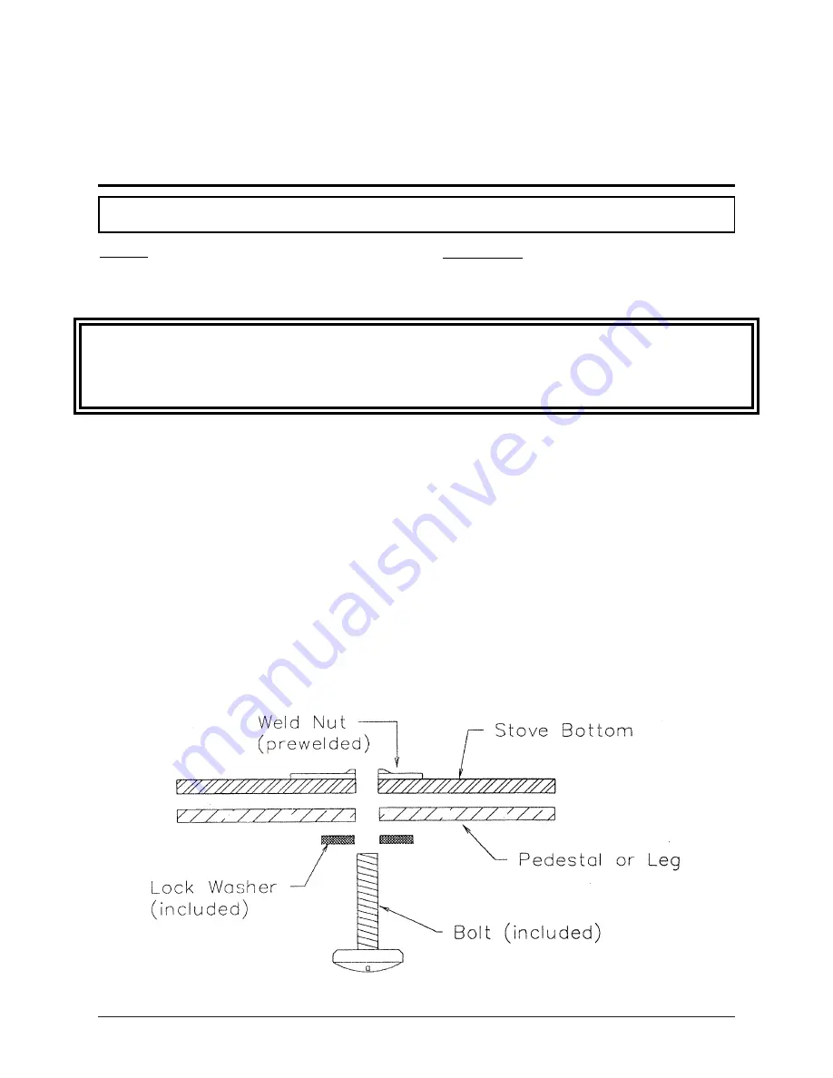
2. Locate the Leg mounting holes according to Figure 1, 2 or 3, depending on the model you
purchased. Please note that each hole has a weld nut on the inside of the stove bottom. Locate the packages
of bolts provided with this leg kit.
3. Attach the legs to the stove bottom using the method shown in Figure 2. Note: For the front legs, the
decorative side of the legs (polished side on gold plated legs) should be facing the front of the unit. For the
rear legs, the decorative side of the legs should be facing the rear of the unit.
4. Thread each bolt into the weld nut by hand; making sure that the bolt and nut thread pattern are not cross-
threaded.
5. Hand tighten each bolt.
6. Tighten using an adjustable wrench.
7. Lift the unit to its upright position.
Caution
If any part of the appliance is damaged during this installation, you will be responsible for the replacement costs. High
Energy Manufacturing Ltd. does not guarantee or warrant any parts that you damage during this installation.
Installation Instructions
Содержание J1000B
Страница 2: ......
Страница 8: ...Page vi 1998 2006 Edition ...
Страница 16: ...Page 8 1998 2006 Edition ...
Страница 20: ...Page 12 1998 2006 Edition ...
Страница 36: ...Page 28 1998 2006 Edition ...
Страница 38: ...Inside the Room and Recessed in an Interior Chase Page 30 1998 2006 Edition Recessed in an Exterior Chase ...
Страница 39: ...Corner Installation Page 31 1998 2006 Edition Installation requires standoffs to maintain clearances ...
Страница 44: ...Page 36 1998 2006 Edition ...
Страница 45: ...Page 37 1998 2006 Edition ...
Страница 46: ...VIII 5 Jamestown Control Panel Page 38 1998 2006 Edition ...
Страница 61: ...Page 53 1998 2006 Edition ...
Страница 62: ...Page 54 1998 2006 Edition ...
Страница 63: ...Page 55 1998 2006 Edition ...
Страница 64: ...Page 56 1998 2006 Edition ...
Страница 69: ...Page 61 1998 2006 Edition ...
Страница 70: ...Page 62 1998 2006 Edition ...
Страница 79: ...Appendix A 3 1998 2006 Edition ...
Страница 80: ...Appendix A 4 1998 2006 Edition ...
Страница 81: ...Appendix A 5 1998 2006 Edition ...
Страница 82: ...Appendix A 6 1998 2006 Edition ...
Страница 84: ...Appendix B 2 1998 2006 Edition ...
Страница 86: ...APPENDIX D EXHAUST BLOWER ASSEMBLY MODEL J1000 Appendix D 1 1998 2006 Edition Complete Assembly is Part 07DAA ...
Страница 87: ...APPENDIX E AUGER MOTOR BRACKET INSTALLATION Appendix E 1 1998 2006 Edition ...
Страница 90: ...Appendix F 3 1998 2006 Edition ...
Страница 93: ...APPENDIX H J1000 CROSSFLOW FAN Part 07EEG Appendix H 1 1998 2006 Edition ...
Страница 94: ...APPENDIX I 1 EXHAUST BLOWER ASSEMBLY MODEL J1000 Appendix I 1 1998 2006 Edition ...
Страница 96: ...SERVICE RECORD DATE SERVICED BY DESCRIPTION ...


