26
Force Control Products
d.
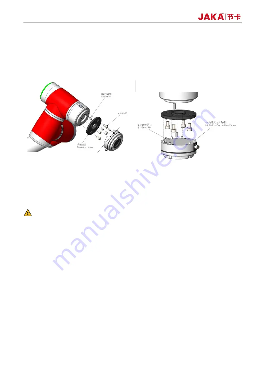
Fasten the sensor to the mounting flange. Use the positioning pins to position the sensor and the
mounting flange, and check that the mounting direction of the sensor is consistent with the use
direction of the device. Fasten the sensor with six embedded screws. Insert a 3mm Allen key into the
mounting hole on the sensor tool end flange. Turn it in the direction of the right-hand thread to secure
the screw in place.
Figure 2-21 Installation of the Sensor to the Robot
e.
Connect the tool interface of the robot to the sensor tool end flange. The sensor tool end flange comes
with four M6 screw holes and φ6 pin holes for connecting device or tools. The positioning pins for the
sensor tool end flange make it easy to install the device and tools repeatedly, and they will not affect
sensor performance if not used.
WARNING:
Do not use screws other than those provided with this product. Using other screws may cause irreversible
damage to the sensor or a robot fault.
2.1.4.3 Wiring of the Sensor
This sensor is connected via USB, that is, you need to connect the sensor USB to the USB port on the control
cabinet panel.
The connecting cable is provided with the product. It is a multicore cable, and its interface matches the cable
interface on the sensor. Align the connector of the multicore cable with the cable connector of the sensor and
push it in (see Figure 2-22). Then tighten the threaded connection shell of the multicore cable interface to
prevent the cable from loosening, achieving IP64 performance. During installation, each cable core should be
wired in strict accordance with the specified core color definitions (the wiring diagram is shown in Figure 2-23).
Be careful not to connect the positive and negative of the power supply in reverse, or the sensor will be
damaged.
运行指示灯
Status light
电源指示灯
Power light
Содержание Zu Series
Страница 1: ...JAKA ROBOTICS Force Control Products JAKA Se and JAKA Sp...
Страница 3: ......
Страница 4: ......
Страница 17: ...Version 3 1 0 13 M3 2 0 M4 4 0 M5 8 0 M6 13 0 M8 35 0...
Страница 41: ...Version 3 1 0 37 Figure 2 36 Installation and Dimensions of the Force Sensor Indicator light...
Страница 61: ...Version 3 1 0 57 Figure 3 8 Force Display Interface of the App...
Страница 75: ...Version 3 1 0 71 Figure 3 19 Force Display Interface of the App...
Страница 79: ...Version 3 1 0 75 Figure 3 21 Collision Detection Function Settings of JAKA Zu Sp...


