34
34
34
34
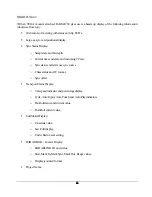
!
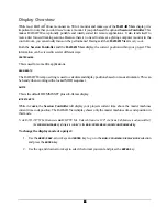
Record time remaining.
!
Disk Mode.
!
SCSI activity indicator.
!
Track display for audio waveform data.
!
Track naming area, inputs, outputs.
!
Current digital format display.
Session Controller Display
The
Session Controller
has a 2 x 16 character display that is used to display the current time code position in
the project, all RADAR
24 menus and dialogs. The default display shows the current time code location in
the standard HH:MM:SS:FF plus sub-frames format. When menu functions are accessed using the
MENU/PREV
key or by pressing a direct access key, the display becomes the central navigation system for
RADAR
24. The contents of this display are mirrored on
RADAR View
with the exception of the default
display.
Indicators
Metering and other indictors are provided on the
RADAR View
display and also on the optional
Meterbridge 24
and
Meterbridge 48,
either of which can be attached to the
Session Controller
professional remote.
METERING
Input signal is displayed on 20 segment LED meters with a scale ranging from below –55 to 0, which is the
maximum input level. A clip LED with variable hold time is also provided to help warn of impending digital
distortion. The clip LED hold time setting can be changed in the
MAIN / PREFS MENU / CLIP HOLD TIME
dialog.
STATUS
Additional LED indicators provided on each channel of the
Meterbridge 24
and
Meterbridge 48
include:
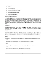
!
ARM
Red-flashing LED indicators identify tracks that are armed and ready for recording.
!
INPUT
Steady state yellow LED indicators identify tracks currently in input monitoring mode.
!
SOLO
Steady state green LED indicators identify tracks that are currently soloed.

