background image

iCU-DC / iCU-EC Operating Instructions 


Page - 9 

4

  Hardware description 


4.1  Front side 


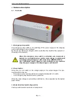
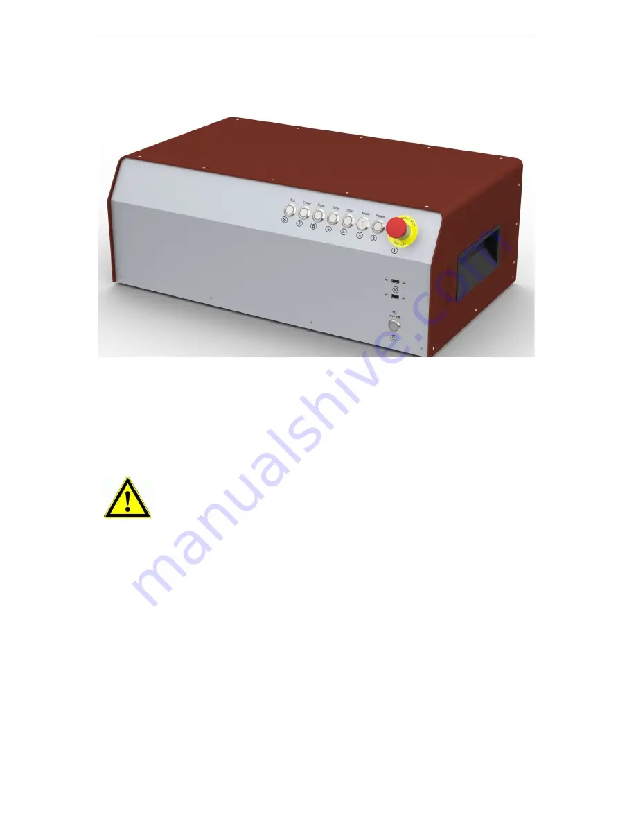
1 -  Emergency stop switch 

The  emergency  stop  switch  is  for  switching  off  the  power  supply  to  the  stepping 
motor output stage in case of danger.   
By this we are referring to dangers which could affect the health of the operator or 
the safety of the machine.  


2 -  Power button 

Using  the  you  can  switch  on  the  voltage  supply  to  the  output  stages.  The  pre-
requirements for this are: 

The power source must be switched on using the backwards “on” switch. 


The emergency stop switch must be “pulled out”.


When the main voltage is successfully switchted on, this is signalled by the lighted 
power button. 


3 -  Mode Selection Switch (Key switch) 

This key switch selects Automatic or Setup mode. 


When  the  emergency  stop  switch  is  activated,  axle  movement  is 
braked in a controlled manner and the main voltage is switched off 
according to Stop Category 1


with a time delay (DIN EN 60204-1). 

The  115/230VAC  power  supply  is  still  connected  to  the  machine.


Only the power supply to the output stage is switched off.


Содержание iCU-DC

Страница 1: ...isel Germany AG D 36124 Eichenzell Bürgermeister Ebert Str 40 06659 981 0 06659 981 776 CNC Servo Controller iCU DC iCU EC Operating Instructions ...

Страница 2: ...h respective company All rights reserved No part of our printed materials may be reproduced in any form print photocopy or any other process or processed duplicated or disseminated via electronic systems without written permission from isel Germany AG Manufacturer isel Germany AG Bürgermeister Ebert Straße 40 D 36124 Eichenzell Tel 49 0 6659 981 0 Fax 49 0 6659 981 776 Email automation isel com ht...

Страница 3: ... Technical data 8 4 Hardware description 9 4 1 Front side 9 4 2 Back side of iCU DC iCU EC 11 4 3 Structure of iCU DC iCU EC 18 5 Initialisation 19 6 Software 20 6 1 Installation of the initialisation software 20 6 2 Installing ProNC Remote and first steps 22 7 EC Declaration of Conformity 26 8 List of sources 27 9 Index 27 ...

Страница 4: ...or integration into an existing network and can also be used for remote maintenance The NC controller core makes it possible to interpolate up to 6 axles linear circular or helix and online and Lock Ahead belt processing are also available Using the software ProNC individual axles can be controlled as handling axles besides the interplating axles The iCU DC CAN Controllers can drive up to 6 brushe...

Страница 5: ... measurement system encoder All work must only be done by authorised specialist personnel with regard to the regulations of the electrical industry as well as accident prevention regulations Before opening the housing or doing any work on the electrical installation you must unplug the power cable Assembly and use of equipment must be carried out according to the norms of the Declaration of Confor...

Страница 6: ...ere the cross section of the protective grounding shall not be less than 10 mm2 copper or 16 mm2 aluminum has e g electrical distribution of the building Please instruct an electrician with these implementation When using the Residual Current circuit Device RCD for line fuses fault current delimitation Do not use an RCD with AC characteristics Using a frequency inverter and choppered power stages ...

Страница 7: ...ug etc Remote control software from Version 1 46 6 6 optional ProNC Operating Instructions Optional Frequency converter SKC750 SKC1500 for main spindle drive max 4 axles possible Scope of delivery iCU EC Art No 354002 20X10 iCU EC servo controller as a tabletop device with the following components o max 6 integrated iMD20 performance output stages for brushless DC servo motors 2 o Control computer...

Страница 8: ...egory 3 PL d Protection type IP20 Environment temperature 0 C to 50 C Storage temperature 20 C to 65 C Air humidity max 90 non condensating Safety functions Can be integrated into higher level emergency stop circuits hood control spindle control I O component group 4 digital inputs 8 digital outputs 4 relay outputs 4 electrical outputs 1 x 115 230 V relay output max 6A Control computer 1 8 GHz pro...

Страница 9: ...requirements for this are The power source must be switched on using the backwards on switch The emergency stop switch must be pulled out When the main voltage is successfully switchted on this is signalled by the lighted power button 3 Mode Selection Switch Key switch This key switch selects Automatic or Setup mode When the emergency stop switch is activated axle movement is braked in a controlle...

Страница 10: ...ontrol program If no user program is open when you press the Start button ProNC or Remote will request you to select a user program 5 Stop button Pressing the interrupts a running user program axle movement You can then resume the user program axle movement by pressing the Start button 6 Cover button This button is used to open the hood if there is one The hood can only be opened when the conditio...

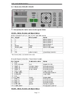
Страница 11: ... grounding conductor Each motor phase is connected via two wires Encoder Signal connection 15 pole Sub D socket Pin Signal Cable wire colour Name 1 n a 2 VCC_Encoder red Digital 5V DC 3 ENC_Z orange black Encoder track Z 4 ENC_B brown black Encoder track B 5 ENC_A Grey black Encoder track A 6 VCC_Logic Logic 24V DC 7 LIMIT_SW1 End position switch 1 8 GND_24V Logic GND 9 n a 10 D_GND black Digital ...

Страница 12: ...tion 15 pole Sub D socket Pin Signal Cable wire colour Name 1 HALL_A _IN yellow Hall Signal A 2 VCC_Encoder red Digital 5V DC 3 ENC_Z orange black Encoder track Z 4 ENC_B brown black Encoder track B 5 ENC_A Grey black Encoder track A 6 VCC_Logic Logic 24V DC 7 LIMIT_SW1 End position switch 1 8 GND_24V Logic GND 9 HALL_B_IN white Hall Signal B 10 D_GND black Digital GND 11 ENC_Z orange Encoder trac...

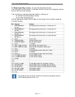
Страница 13: ...cy Stop channel 2 connection 2 1 4 EMERGENCY STOP_2 Emergency Stop channel 2 connection 2 2 5 24V 24 V DC 6 POWER BTN Power button input 7 POWER LAMP Power light output 8 24V 24VDC 9 KEY SWITCH Test Key switch test mode input 10 KEY SWITCH Auto Key switch automatic mode input 11 24V 24VDC 12 ACK_1 Acknowledge button channel 1 input 13 24V 24VDC 14 ACK_2 Acknowledge button channel 2 input 15 COVER ...

Страница 14: ...ACK light switch output 7 24V 24VDC 8 ACK_1 Acknowledge button channel 1 input 9 24V 24VDC 10 ACK_2 Acknowledge button channel 2 input 11 COVER SWITCH 1 Cover button input 1 12 COVER SWITCH 1 Cover button output 1 13 COVER SWITCH 2 Cover button input 2 optional 14 COVER SWITCH 2 Cover button output 2 optional 15 n a The length of the connection cable for the additional operating console is max 5m ...

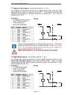
Страница 15: ...E1 8 when setting the signalling in the user interface Remote ProNC These inputs are already wired inside the controller to their modules and can no longer be used by the operator Remote Safety circuit interface 8 pole left to right Using this interface you can integrate the emergency stop circuit of the equipment output unit into a higher level safety circuit system Here you can also tap the anal...

Страница 16: ...f the first output port A1 1 A1 8 when setting the signalling in the user interface Remote ProNC The outputs A1 5 A1 8 are already wired inside the controller to their modules and can no longer be used by the operator When using intuctance an free wheeling diode is necessarily Digital Relay Outputs 8 pole left to right A2 1 A2 4 The installed I O component group has a second digital output port wi...

Страница 17: ...a the SK module iSM5 and then the power supply of 115 230V is switched to the working spindle e g UFM 500 750 1050 via a relay Take note of the CAN I O module table defining assigned spindle start signals in section 4 2 Connection for main spindle drive optional Here at this connection a processing spindle with RPM control is attached asynchronous motor The optional frequency converter is located ...

Страница 18: ...nction keys module for operating elements buttons switches on the front side of the controller iMD10 iMD20 output stages for brushed DC servo motors brushless DC servo motors Powerpack 115 230VAC 24V DC 100W for Logic Powerpack 115 230VAC 12V DC 60W for PC Powerpack 115 230VAC 48V DC 1000W for motors CAN I O 16 16 I O module Frequency converter SKC optional ...

Страница 19: ...s are correctly attached to the controller Initialisation Use the power switch on the back to turn on the controller Turn on the control computer using the green button on the back this button should now light up in green the computer will now boot up the installed operating system Installing the control software if not already installed Remote or ProNC 1 from Version 1 46 6 6 Installing the initi...

Страница 20: ...utput stage iMD10 or ACSetup exe 3 for brushless DC servo motors with motor output stage iMD20 and Please proceed as follows to install the initialisation programs after the fact 1 Connect the ProNC Remote installation medium supplied CD or USB stick to the control computer 2 The following auto start window will appear when installing from CD If the auto start window does not appear please open Wi...

Страница 21: ... initialisation program DCSetup exe ACSetup exe either via the shortcut on the Windows Desktop or via the start menu item Start Programs ACSetup DCSetup ACSetup You can find information about the parameterisation of the iMD10 performance output stage in the handbook 1 DC servo positioning module with CanOpen Interface UVE 8112 iMD10 Open the file dcsetup_ger pdf using the start menu option You can...

Страница 22: ...not installed any software yet please proceed as follows to install the programs after the fact 1 Connect the ProNC Remote installation medium supplied CD or USB stick to the control computer 2 The following auto start window will appear when installing from CD If the auto start window does not appear please open Windows Explorer and open the main directory of the installation medium Double click ...

Страница 23: ...select the item CAN Bus Control to install the CAN bus software module After installation is complete click on Finish to close the auto start menu 4 Use the configuration program CANSet exe shortcut on the Windows Desktop or via the start menu option Start Programs isel CAN CNC Control CANSet to set up machine specific parameters CAN interface axles used axle type etc ...

Страница 24: ... file You must then later use this file in the ProNC Remote operating interface as the motion control module DLL initialisation file 5 Start the user interface ProNC exe either via the shortcut on the Windows Desktop or via the start menu option Start Programs CNC workbench ProNC ...

Страница 25: ...at you saved before Click on the button Save Initialise to save the settings and put the controls into their start settings 6 Carry out a Software Reset and a Reference Movement to check the correct function of the machine and the system For further information on configuring the ProNC Remote please refer to the programs online help sections Help menu or F1 key ...

Страница 26: ...sting and measurement techniques Electrical fast transient burst immunity test EN 61000 4 5 2007 EMV Prüf und Messverfahren Prüfung der Störfestigkeit gegen energiereiche Impulse Surge EMC Testing and measurement techniques Surge immunity test EN 61000 4 11 2005 EMV Prüf und Messverfahren Prüfung der Störfestigkeit gegen Spannungs einbrüche Spannungsunterbrechungen EMC Testing and measurement tech...

Страница 27: ...ny AG iPC25 Operating Instructions 07 2014 Operating instructions and manuals can be downloaded at www isel data de manuals 9 Index A ACK 10 ACSetup 19 B BLDC Servo motors 7 C CANSet exe 19 Cover button 10 D door lock 14 E emergency stop switch 9 Encoder 11 12 I iMD20 8 initialisation file 24 initialisation software 20 Installation 20 M Mode Selection Switch 9 Motor connection 11 12 P power button...

Отзывы: