iCU-DC / iCU-EC Operating Instructions
Page - 14
➂
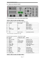
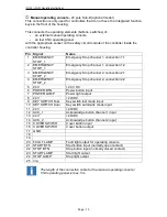
Additional operating console
- 15 pole Sub-D (optional model)
We use this connection when an additional Isel operating console is connected.
Pin Signal
Name
1
EMERGENCY
STOP_1
Emergency Stop channel 1, connection 1.1
2
EMERGENCY
STOP_1
Emergency Stop channel 1, connection 1.2
3
EMERGENCY
STOP_2
Emergency Stop channel 2, connection 2.1
4
EMERGENCY
STOP_2
Emergency Stop channel 2, connection 2.2
5
GND
GND operating console
6
LAMP ACK
ACK light switch output
7
24V
+24VDC
8
ACK_1
Acknowledge button channel 1 input
9
24V
+24VDC
10 ACK_2
Acknowledge button channel 2 input
11 COVER SWITCH 1
Cover button input 1
12 COVER SWITCH 1
Cover button output 1
13 COVER SWITCH 2
Cover button input 2 (optional)
14 COVER SWITCH 2
Cover button output 2 (optional)
15 n/a
The length of the connection cable for the additional operating console is
max. 5m.
➃
Cover
- Sub-D 9 pole socket
At this connection, you can integrate the
of the attached machine into the controller’s
safety circuit.
Pin
Name
1
+Coil, normally closed contact
2
Switch 1, 1.1
3
Switch 1, 1.2
4
Switch 2, 2.1
5
Switch 2, 2.2
6
-Coil, normally closed contact
7, 8, 9 not used


