iCU-DC / iCU-EC Operating Instructions
Page - 13
➁
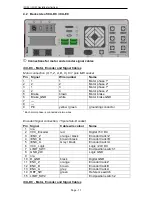
Manual operating console
- 25 pole Sub-D (optional model)
This connection is only used for controllers that do not have the integrated function
keys in the front of the housing.
This connects the operating elements (buttons, switches) of:
-
an external manual operating console
-
an Isel CNC operating panel
with the appropriate socket on the safety circuit module of the controller inside the
controller housing.
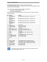
Pin Signal
Name
1
EMERGENCY
STOP_1
Emergency Stop channel 1, connection 1.1
2
EMERGENCY
STOP_1
Emergency Stop channel 1, connection 1.2
3
EMERGENCY
STOP_2
Emergency Stop channel 2, connection 2.1
4
EMERGENCY
STOP_2
Emergency Stop channel 2, connection 2.2
5
24V
+24 V DC
6
POWER BTN
Power button input
7
POWER LAMP
Power light output
8
24V
+24VDC
9
KEY SWITCH Test
Key switch test mode input
10 KEY SWITCH Auto
Key switch automatic mode input
11 24V
+24VDC
12 ACK_1
Acknowledge button channel 1 input
13 24V
+24VDC
14 ACK_2
Acknowledge button channel 2 input
15 COVER SWITCH
Cover button input
16 COVER SWITCH
Cover button output
17 GND
18
19
20 FAULT LAMP
Fault light output for operating console
21 START BTN
Start button input (normally open contact)
22 STOP BTN
Stop button input (normally closed contact)
23 START LAMP
Start llight output
24 STOP LAMP
Stop light output
25 n/a
The length of the connection cable for the manual operating console /
CNC operating panel is max. 5m.


