iCU-DC / iCU-EC Operating Instructions
Page - 15
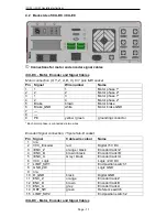
➄
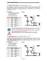
Digital Inputs
- 8 pole, left to right E1.1
–
E1.4
The installed I/O component group has one digital input port. The inputs E1.5 - E1.8)
are already partially wired internally and occupied by signal inputs and not usable by
the user. The digital inputs E1.1 - E1.4 may be assigned by the user.
Properties
- Optoelectronic coupler inputs
- Input current approx. 8mA
Wiring
Pin
Input
Name
1
In 1
Input E1.1
2
VCC
+24VDC
3
In 2
Input E1.2
4
VCC
+24VDC
5
In 3
Input E1.3
6
VCC
+24VDC
7
In 4
Input E1.4
8
VCC
+24VDC
Note the default assignment of the first input port (E1.5 - E1.8) when
setting the “signalling” in the user interface Remote / ProNC.
These inputs
are already wired inside the controller to their modules and can no longer
be used by the operator!
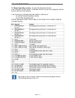
➅
Remote
-
Safety circuit interface, 8 pole, left to right
Using this interface, you can integrate the emergency stop circuit of the equipment
output unit into a higher-level safety circuit system. Here you can also tap the analog
output signal 0...10V of the integrated I/O module.
Pin
Signal
Name
1
EMERGENCY
STOP_1
External emergency stop channel 1, connection 1.1
2
EMERGENCY
STOP_1
External emergency stop channel 1, connection 1.2
3
EMERGENCY
STOP_2
External emergency stop channel 2, connection 2.1
4
EMERGENCY
STOP_2
External emergency stop channel 2, connection 2.2
5
ANA_GND
Analog GND
6
ANA_0_10V
Analog 0…10V DC
7
----
8
----


