Operation Manual 7310 EPSHP
14
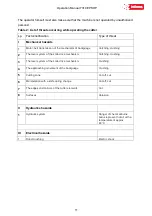
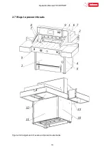
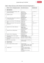
Table 3: Safety measures used to eliminate hazards (according to Figure 3)
Factors and / or dangerous places Security measures
Identification
I MECHANICAL
1. The lever assembly mechanism of the
pressure beam drive
Fixed cover
Machine body
Emergency stop
1, 3, 4, 10, 11
2
9
2. Hydraulic system
Machine body
Fixed cover
Front table
Emergency stop
2
3, 4, 10, 11
8
9
3. The belt drive for the drive mechanism of
the backguage beam
Machine body
Front table
Emergency stop
2
8
9
4. The screw mechanism of the backguage
drive
Cutter body
Fixed cover
2
6, 12
5. Motor, lever mechanism of the knife drive
mechanism
Fixed cover
Machine body
Front table
Emergency stop
1, 3, 4, 10, 11
1, 2
8
9
6. Approach move of the knife beam
Fixed cover
Safety curtain
Two-handed device
Emergency stop
1
7
5
9
7. Approach move of clamp beam
Fixed cover
Safety curtain
Two-handed device
Emergency stop
1
7
5
9
8. Approach move of backguage
Fixed cover
Emergency stop
1, 6
9
9. Manipulation with a knife during its
replacement
Transport handles
Special protective packaging
10. Sharp edges and corners of the cutter
elements
Refraction, dullness, rounding
11. Uneven or rough surfaces
Precise workpiece machining
Paint coatings
II ELECTRICAL
1. Direct contact of active elements
Closed housing
Partially reduced voltage supply
to the control system up to 24V
AC/DC
2, 13
2. Indirect touch
Protection against indirect
contact according to PN-EN
60204-1.
Continuity of the protective
conductor
Содержание INT-GU-07310EPSHP
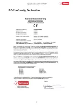
Страница 5: ...Operation Manual 7310 EPSHP 5 EC Conformity Declaration...
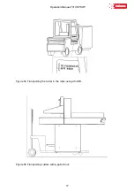
Страница 42: ...Operation Manual 7310 EPSHP 42 Figure 26 Figure 27...
Страница 55: ...Operation Manual 7310 EPSHP 55 Figure 43 Adjusting elements of backguage...
Страница 61: ...Operation Manual 7310 EPSHP 61 Figure 50 Lubrication point of the knife assembly lever...
Страница 66: ...Operation Manual 7310 EPSHP 66 PROGRAM MODULE OPERATOR MANUAL DOP B07S410 7...

