Operation Manual 7310 EPSHP
53
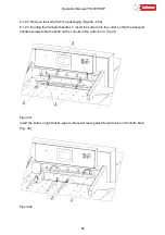
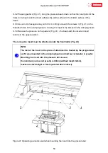
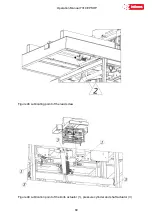
8.3.2 Pressing pedal 2 (Fig. 41), bring the pressure beam down so that the insert pins hit the
holes in the beam and the insert adheres the entire surface to the bottom surface of the
beam.
8.3.3 Use a 3-mm hexagonal key with 3 mm to firmly screw in the screws 3 (Fig. 41) in the
threaded holes in the clamping beam, causing the insert to be blocked in the clamping beam.
8.3.4 Release the pressure on the pedal 2 (Fig. 41) - the beam with the inserted insert
returns to the upper position
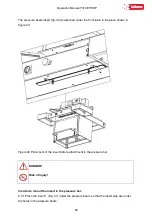
The removable insert must be attached under the front table! (Fig. 40)
INFO
The lack of the insert in the place of attachment is treated by the programmer
as if it was mounted in the clamping beam and narrow cut (waste) is greater.
Mounting the insert into the pressure bar causes;
the minimum narrow cut (waste) is 40mm (without insert 22mm),
maximum stack height is 76mm (without 80mm insert).
Figure 41 Operating elements used when mounting the insert into the pressure bar
Содержание INT-GU-07310EPSHP
Страница 5: ...Operation Manual 7310 EPSHP 5 EC Conformity Declaration...
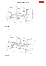
Страница 42: ...Operation Manual 7310 EPSHP 42 Figure 26 Figure 27...
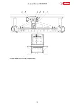
Страница 55: ...Operation Manual 7310 EPSHP 55 Figure 43 Adjusting elements of backguage...
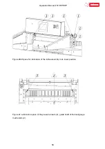
Страница 61: ...Operation Manual 7310 EPSHP 61 Figure 50 Lubrication point of the knife assembly lever...
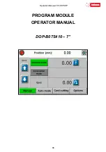
Страница 66: ...Operation Manual 7310 EPSHP 66 PROGRAM MODULE OPERATOR MANUAL DOP B07S410 7...

