Operation Manual 7310 EPSHP
27
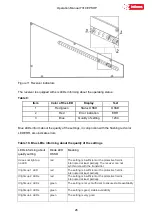
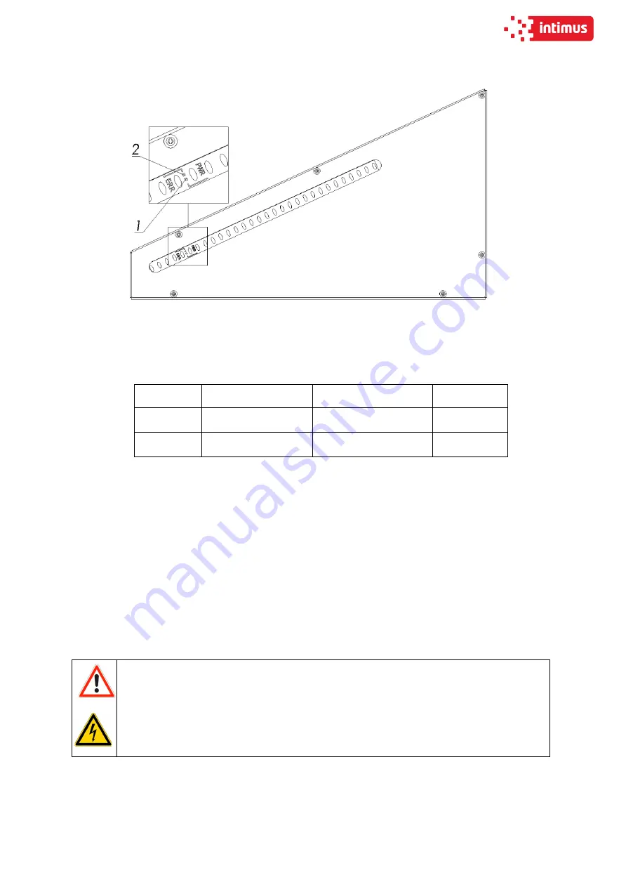
Figure 12 Transmitter Indicators
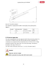
The transmitter is equipped with two LEDs informing about the operating status:
Table 11:
Position
LED diode colour
Indication
Text
1
yellow
Work status indicator
PWR
2
red
Error indication
ERR
5.3 Electrical apparatus
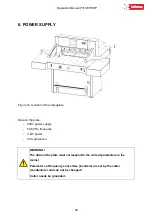
The cutter is supplied with a five-core copper wire with 2.5 mm2 wire cross-section. The
user's duty is to install the cutter to the electrical network with 20 A safeguards. For
connecting, use a copper wire with a cross-sectional area of 2.5 mm2 or more. Voltage
fluctuations should be in the range of 90-110% of the rated voltage, and frequency
fluctuations in the range of 50 Hz ± 2%.
The cutter can be connected to a five-core, L1, L2, L3, N, PE electric network.
DANGER!
Dangerous electrical voltage!
Before opening the housing, switch off the main switch!
Содержание INT-GU-07310EPSHP
Страница 5: ...Operation Manual 7310 EPSHP 5 EC Conformity Declaration...
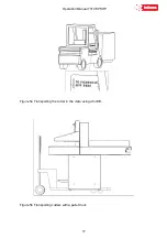
Страница 42: ...Operation Manual 7310 EPSHP 42 Figure 26 Figure 27...
Страница 55: ...Operation Manual 7310 EPSHP 55 Figure 43 Adjusting elements of backguage...
Страница 61: ...Operation Manual 7310 EPSHP 61 Figure 50 Lubrication point of the knife assembly lever...
Страница 66: ...Operation Manual 7310 EPSHP 66 PROGRAM MODULE OPERATOR MANUAL DOP B07S410 7...

