Operation Manual 7310 EPSHP
25
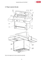
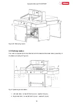
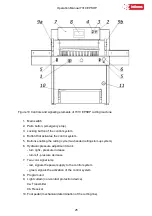
Figure 10 Controls and signaling elements of 7310 EPSHP cutting machine
1. Main switch
2. Palm button, (emergency stop)
3. Locking button of the control system
4. Button that activates the control system.
5.
Buttons enabling the cutting cycle (two-handed cutting start-up system)
6. Hydraulic pressure adjustment crank
- turn right - pressure increase
-
turn left - pressure decrease
7.
Two-color signal lamp
-
red, signals the power supply to the control system
- green, signals the activation of the control system
8. Program unit
9. Light curtain (non-contact protection device)
9a. Transmitter
9b. Receiver
10. Foot pedal (mechanical determination of the cutting line).
Содержание INT-GU-07310EPSHP
Страница 5: ...Operation Manual 7310 EPSHP 5 EC Conformity Declaration...
Страница 42: ...Operation Manual 7310 EPSHP 42 Figure 26 Figure 27...
Страница 55: ...Operation Manual 7310 EPSHP 55 Figure 43 Adjusting elements of backguage...
Страница 61: ...Operation Manual 7310 EPSHP 61 Figure 50 Lubrication point of the knife assembly lever...
Страница 66: ...Operation Manual 7310 EPSHP 66 PROGRAM MODULE OPERATOR MANUAL DOP B07S410 7...

