-378-
11 Appendix
4)
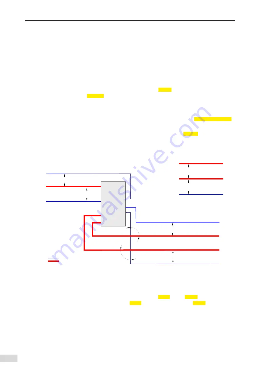
The motor cables must be routed away from other cables. The motor cables of several servo drives
can be routed in parallel.
5) It is recommended that the motor cables, power input cables and control cables be routed in
different cable duct. The motor cables and other cables cannot be routed in parallel for a long
distance. This is to prevent the electromagnetic interference caused by rapid change of the drive
output voltage.
6) If the control cable must pass through the power cable, make sure the angle between them is close
to 90 degrees. Other cables cannot pass through the servo drive.
7) Power input and output cables and signal cables (such as control cables) of the servo drive should,
if possible, be laid vertically rather than in parallel.
8)
Cable ducts must be in good connection and well grounded. Aluminum cable ducts can be used to
improve equal potential.
9) The grounding plane of different equal potential must be connected properly with cables of above
16 mm
2
.
10) The filter, the servo drive and the motor must be properly connected to systems, with the
conductive metal kept in full contact.
■
The recommended wiring diagram is shown below.
Servo drive
Min
.:
200 mm
Main circuit cable
Power cable
Regenerative
resistor cable
Power cable
Main circuit cable
90 °
90 °
Control cable
Control cable
Main circuit cable
Encoder cable
Control cable
Communication cable
Communication cable
Min
.:
500 mm
Min
.:
300 mm
Min
.:
500 mm
Min
.:
500 mm
Min
.:
500 mm
11.1.7 Solutions to Leakage Current
The servo drive outputs high-speed pulse voltage, which may generate high-frequency leakage current.
It is recommended to use a residual current device (RCD) with action current no less than 100 mA. If
multiple servo drives share the same RCD, the action current of this RCD must be no less than 300 mA.
Factors that affect the leakage current are listed as follows:
■
Distributed capacitance of the motor
■
Carrier frequency
■
Type and length of the motor cables.
■
EMI filter
Содержание SV660
Страница 178: ...177 6 Gain Tuning Figure 6 18 Example of the waveform...
Страница 359: ...358 10 Application Cases c Click OK d Click Yes...
Страница 360: ...359 10 Application Cases e Click OK f Click No...
Страница 362: ...361 10 Application Cases...
Страница 366: ...365 10 Application Cases 7 2 Controlling the servo operations through the PLC a Create a PLC program...
Страница 370: ...369 10 Application Cases b Add parameters to be monitored to monitor these parameters during PLC running...


