


Page 17
EN
Chapter 4 Assembly and function
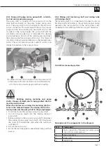
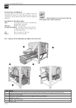
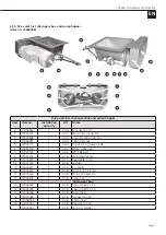
4.5.2 Pump unit (pump motor, pump shaft, rotor/sta-
tor and mortar pressure gauge)
The pump shaft is connected to the pump motor via the
drive shaft and rotates in the pump hopper during oper-
ation. The pump shaft is also connected to the rotor via a
plug-in connection. The assembly with the mortar pressure
gauge and the hose coupling are fixed with two tie rods
mounted on the pump hopper. The pump shaft and the
rotor/stator can be pulled out or dismantled for cleaning
and maintenance. Switch off the machine and disconnect
the mains plug before carrying out this work. The choice of
rotor/stator (see accessories) depends on the planned appli-
cation. The mortar pressure gauge is used to monitor and
display the pressure in the conveyor hose.
1
2
3
This diagram shows the connection from the pump motor
to the pump shaft, the rotor/stator (2) and the assembly
with the mortar pressure gauge and hose coupling.
!
DANGER
Rotating mixing, metering and pump
shafts. Danger of death due to being pulled into the
machine and crushed.
When the motors are running, the metering shaft ro-
tates in the material hopper, the mixing shaft in the
mixing tube and the pump shaft in the pump hopper.
• Do not reach into the rotating mixing or pump shaft.
• Do not bring any objects into the rotating mixing or
pump shaft.
1. Before working on the mixing or pump shaft, disconnect
the external power supply (main switch off). Only loosen
the screw of the protective grids when the machine is
switched off.
2. Pull out the mains plug.
3. Secure the machine against unexpectedly being switched
back on.
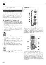
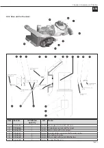
4.5.3 Mixing unit (metering shaft and mixing tube
with mixing shaft)
The metering shaft (1) is connected to the mixer motor via
the drive shaft and rotates in the metering hopper during
operation. The mixing shaft (2) in the mixing tube is also
connected to the metering shaft via a plug-in connection.
1
2
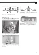
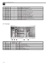
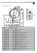
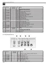
4.5.4 Water measuring system
1
2
3
4
5
6
8
7
Description of the components in the diagram
Item
Component
1
Main connection of the external water supply
(min. 2.5 bar water pressure)
2
Pressure reducer
3
Drain cocks
4
Needle valve


