Page 24
EN
Chapter 4 Assembly and function
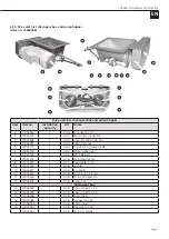
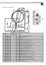
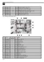
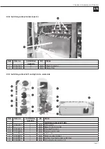
4.9 Spare parts and diagrams
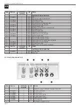
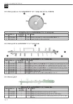
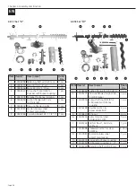
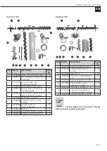
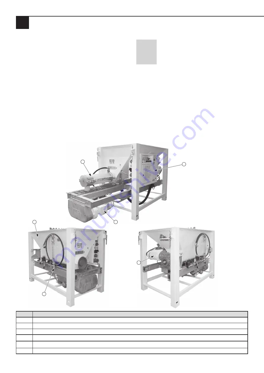
The spare parts for the small silo inoCOMB Cabrio are
marked with numbers in the following pictures. The indi-
vidual items are described in the table under the respective
diagrams.
Description of the table columns:
Item:
Corresponds to the number in the drawing
designating a spare part.
Item no.:
INOTEC item number.
Installation quantity:
Number of parts in this position
as they are installed in the original small
silo inoCOMB Cabrio.
UQ:
Unit of quantity of this item.
Name:
Name of the spare part.
NOTE
Use the order form at the end of this op-
erating manual to order spare parts.
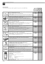
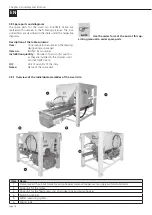
4.9.1 Overview of the individual assemblies of the small silo
1
5
2
4
6
3
Item Name
1
Frame rack with pull-out frame for pump hopper, material hopper, water supply button and vibrator
2
Drive unit for the mixer
3
Drive unit for the feed pump, incl. chain gear box and pump hopper
4
Switching cabinet
5
Water measuring system
6
Mixing tube


