Page 18
EN
Chapter 4 Assembly and function
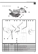
5
Sight glass Water quantity
6
Solenoid valve
7
Cleaning hose connection
8
Water pressure switch
The inlet pressure at the water metering system (min. 2.5
bar) is determined via a water pressure monitor (8). Below
the minimum pressure (2.5 bar), the machine malfunctions
and the illuminated button on the switching cabinet lights
up. After the fault has been rectified, the illuminated button
flashes and must be acknowledged by pressing it once.
4.5.4.1 Installing the water measuring system
1. Connect the supply hose to the external water supply.
2. Open the water valve until a steady water jet comes out
of the hose in order to both clean the water hose of dirt
and ventilate it.
3. Then close the water valve on the external water supply.
4. Connect the external water hose to the GEKA coupling
of the water fitting (1).
5. Close both the water drainage tap (3) below the pres-
sure reducer and the one below the main connection.
6. Connect the internal water hose to the GEKA coupling
of the mixing tube.
!
WARNING
Water jet.
Risk of injury and risk of property damage due to es-
caping water.
1. Interrupt the external water supply by closing the water
valve.
2. In order to release the pressure (approx. 2 bar), open
the water drainage valve on the water measuring sys-
tem under the pressure reducer.
3. Remove the hose from the external water supply.
4. Do not point the water jet at other people or yourself.
NOTE
Use an external site compressor for
processing reprofiling mortar.
4.6 Connections
4.6.1 Power connections (230 / 400 V)
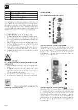
5
4
3
2
1
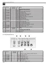
Connections on the switching cabinet left:
CEE appliance plug (400 V) for the central power supply
of the small silo (1), socket (230 V) for connecting an ex-
ternal booster pump (2) if the water pressure is too low
(below 2.5 bar), socket (230 V) for connecting addition-
al appliances (3), remote control socket with cover (4)
and main switch "ON/OFF" (5).
1
2
5
3
4
6
7
8
Connections on the switching cabinet right:
Mounting socket for the level probe in the pump hopper
(1), mounting socket for monitoring the protective grille
(2), mounting socket for monitoring the water pressure and
controlling the solenoid valve (3) on the water measuring
system, socket for the pump motor (4), socket for the mixer
motor (5), socket for the vibrator (6), mounting socket for
the mortar pressure gauge (7) and two unoccupied mount-
ing sockets (8).


