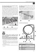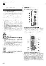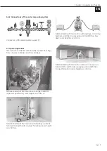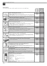
Page 13
EN
Chapter 4 Assembly and function
NOTE
Note the optimum assembly sequence.
The small silo is delivered from the factory with an in-
serted pump hopper.
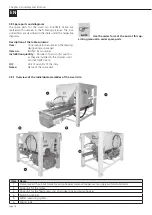
4.3 Sequence of assembly
1. Open the eccentric lock on the base frame below the
water fitting.
2. Unlock the fixing bolt that secures the extendable pump
hopper and pull out the pump hopper.
3. Push the pump shaft into the shaft in the lower area of
the pump hopper and insert it into the Rotex coupling
of the drive shaft.
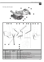
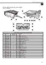
4. Insert the suction flange into the opening provided on
the pump hopper (1). Place the pump unit (rotor/stator)
(2) on the suction flange and connect the pump unit
to the pump shaft (3). Then fit the assembly (4) (pres-
sure flange with mortar pressure manometer and the
hose coupling) to the pump unit. Fix the two tie rods (5)
to the pressure flange with the corresponding screws.
Connect the plug of the mortar pressure gauge (6) to
the plug connection attached to the base frame.
3
2
4
5
6
1


