


RMV Operations Manual Revision Copyright illunis LLC, 2014
Page 26
3.0: Software ICD
Overview
3.1: Software ICD
Serial Interface
SERIAL INTERFACE PROTOCOL
Implementation
Camera communication is accomplished via asynchronous serial communication according to EIA
Standard RS 232 C through the Camera Link cable.
Data rate: Full Duplex, 9600 baud.
1 START bit.
8 DATA bits – The LSB (D0) is transfered first.
1 STOP bit.
No parity.
The RMV software interface (commonly called a Inter-Connect-Description or ICD) was devel-
oped for high reliability applications. The ICD incorporates error checking and a handshake protocol
which responds with either a positive or negative acknowledge signal. The communication path from
frame grabber to the RMV is through the Camera Link cable. The Camera Link committee has specified
that devices connected must first communicate at 9600 baud. This default baud rate is certainly very
slow for devices such as the RMV camera. The RMV has a selectable baud rate for faster communica-
tion speeds.
The RMV microprocessor is a flash programmable device with many features vital to the opera-
tion of the RMV camera. Some of these include:
A hardware UART used for serial communications.
A watchdog timer used to monitor communication errors and system faults.
Onboard RAM and EEPROM for saving camera settings
Parallel data bus for high speed interfaces to the FPGA and NAND FLASH memories
Brown out detection and reset
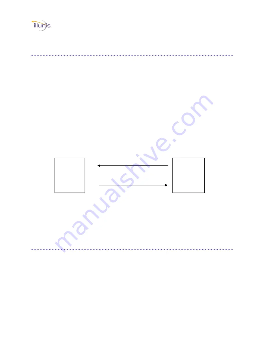
Camera
Capture
Device
Command with checksum
Data and/or ACK/NACK


