4
IBIS-ArcSAR
HARDWARE BREAKDOWN
IDS GeoRadar S.r.l.
Confidential Information - Do Not Distribute
MNG/2017/0016 Rev 1.0 17/ 78
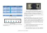
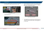
Fig. 15 – Front side of the Power module
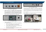
Genset module (
) is provided along with the integrated
generator: it contains the Generator control unit AMF25 which can
start or stop the generator and manage alarm and warning signals
from the generator sensors (e.g. lack of oil, empty tank, etc.). On the
right hand side (see
) there is a horn which activates when
AMF25 alarm/warning is present; AMF25 is already set and ready to
communicate with the PSC board into the Control module;
Fig. 16 – Front side of the Genset module
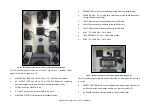
Green module (
17) is associated to solar panels and wind turbine.
It contains following parts:
WIND: it includes the button to brake the wind turbine and the
LEDs to check the charging status and working mode
SOLAR: it includes the switch to turn on the solar panels input
and the LED to check the charging status;
BATTERY: this switch allows the power flowing from the green
sources to the ArcSAR batteries;
Fig. 17 – Front side of the Green module
The Module On blue LED on the upper left of every modules indicates when
they are powered and active. The Power, Control and Green modules turn
on when the Enable switch on Power Module is switched on. The Genset
Module turn on when the Genset switch on Control Module is switched on.
4.3.2
I/O panels
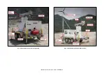
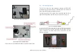
The I/O interfaces are set in two panels, located on the front and rear sides
of the ArcSAR Supply Unit, as shown in Fig. 18
Fig. 18
Figure 1 – Positions of the I/O interfaces panels on IBIS-ArcSAR


