Confidential Information - Do Not Distribute
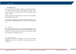
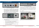
The PSU is composed by drawers which are called modules, placed on the
left side of the ArcSAR Supply Unit. A front door gives access to them (
). Description of the front side of each module follows here below.
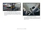
Fig. 13 – Modules on the front side of PSU
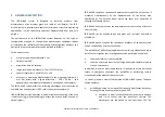
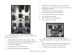
Control module (
): it contains electrical switches which permit
to supply (from left to right) Radar Sensor, Positioner, acquisition
Laptop PC, Panoramic Camera, Genset Module, GPS, AUX1 socket,
AUX2 socket;
Fig. 14 – Front side of the Control module
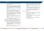
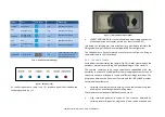
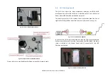
Power module (
): it contains the following components (from
left to right):
AC Input switch: it permits to supply the system by AC voltage
from mains or Generator. The LED is lit up in blue when the
voltage is present.
DC Input switch: it permits to supply the system by DC current
provided by external source. The LED is lit up in blue when the
voltage is present.
Battery: this indicator shows the charge level of the batteries.
The LED is lit up in orange when the batteries are charging;
Enable switch: it permits to supply all the modules of the PSU;
ON/OFF Switch: it interrupts the power supplying of the
system, including the charging of the batteries;
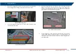
Every time the system is shut down and then supplied again, it is always
necessary to press the enable switch in order to switch on the system
The DC Input switch has to be turned on when for example an external battery
pack is connected to the system. After connecting the external battery pack
and turning on the DC Input switch, the entire system automatically turns off
and it is necessary to press again the Enable switch to restore the system


