background image

1


INTRODUCTION


IDS Ingegneria dei Sistemi S.p.A.  

Confidential Information - Do Not Distribute 


MNG/2017/0016  Rev 1.0        5/ 78 

1


INTRODUCTION 

This document describes the IBIS-ArcSAR system, and particularly refers to 
the  concepts  the  user  should  learn  before  initiating  the  utilization  of  this 
device.  Therefore  we  recommend  to  read  the  entire  document  before 
starting the system. 

If technical assistance is required, please use the contact numbers provided 
on the Appendix of this manual. 

The information contained in this document is confidential and may not be 
used, published or redistributed without the prior consent of IDS Georadar 
Srl. 


1.1


Purpose 

Reading  this  document  will  provide  all  the  necessary  knowledge  to  install 
and maintain the IBIS-ArcSAr system. It particularly presents a step by step 
procedure  to  install  the  system,  information  for  a  safe  use  of  the  system 
and instructions for its general maintenance. 


1.2


Application field 

This  document  applies  to  the  installation  of  the  IBIS  system  in  ArcSAR 
configuration  and  its  use  in  the  field  for  monitoring  of  quasi  static 
phenomena. 


Содержание IBIS-ArcSAR

Страница 1: ...MNG 2017 0016 Rev 1 0 IBIS ArcSAR User manual...

Страница 2: ...2 Symbols 6 2 3 Glossary and acronyms 7 2 4 Reference 7 3 GENERAL DESCRIPTION 8 4 IBIS ArcSAR HARDWARE BREAKDOWN 11 4 1 ArcSAR Trailer 11 4 2 ArcSAR Acquisition Unit 11 4 3 ArcSAR Supply Unit 15 4 4 P...

Страница 3: ...IS Sensor Setup 46 5 9 Panoramic Camera Setup 47 5 10 Supply Unit and Acquisition Unit Connections Setup 47 5 11 Safety Electrical devices Setup 47 5 12 Generator First Setup 48 5 13 Turning on the sy...

Страница 4: ...DISMANTLING AN IBIS ArcSAR SYSTEM 68 7 1 Actions on IBIS Controller and on ArcSAR Laptop 68 7 2 Actions on the ArcSAR Supply Unit 69 7 3 Actions on the Trailer jacks 69 7 4 Get ArcSAR ready to drive...

Страница 5: ...ided on the Appendix of this manual The information contained in this document is confidential and may not be used published or redistributed without the prior consent of IDS Georadar Srl 1 1 Purpose...

Страница 6: ...tion Chapter 4 IBIS ArcSAR Hardware Breakdown Chapter 5 First ArcSAR Setup Chapter 6 First ArcSAR Start Up Chapter 7 Dismantling an ArcSAR system APPENDIX A Disclaimer APPENDIX B Warranty APPENDIX C P...

Страница 7: ...Supply Unit SAR Synthetic Aperture Radar SNR Signal to Noise Ratio SU Subscriber Unit USB Universal Serial Bus 2 4 Reference 2 4 1 Bibliography BD1 MNG 2016 0009 IBIS Controller v 04 02 User Manual BD...

Страница 8: ...sing without needing to access the area to install sensors or optical targets IBIS ArcSAR supplies a continuous displacement map of the entire area It measures simultaneously all the displacements of...

Страница 9: ...nit this module is in charge of giving power supply and control to the Acquisition Unit and to other optional devices such as WIFI antenna and weather station It is composed of Laptop PC it is equippe...

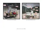
Страница 10: ...Confidential Information Do Not Distribute Fig 1 IBIS ArcSAR system rear and right side Fig 2 IBIS ArcSAR system front and left side...

Страница 11: ...ease the working security when the trailer is parked The supplying of the trailer supports is provided by a cable to connect to the main I O interface panel placed on the rear side of ArcSAR Supply Un...

Страница 12: ...Camera is installed on the top cover of the Radar Sensor Fig 7 and it is automatically supplied by the Positioner Pointing Camera connections consist of an Ethernet wire and a power wire 12Vdc Fig 7...

Страница 13: ...ntal beam can rotate from 180 to 180 with an accuracy of 0 01 Once tilt angle has been defined ArcSAR scans with different angles can be performed to extend or reduce the Radar Sensor field of view Fi...

Страница 14: ...ovided to facilitate the lifting and moving of the Positioner during ArcSAR first configuration The Positioner base has holes placed at every corner to allow the fixing of the whole frame to the Trail...

Страница 15: ...evices included in the ArcSAR Positioner In addition it allows the communication between the field Laptop and the Control Room ArcSAR Supply Unit includes the Power Supply Unit with the ArcSAR battery...

Страница 16: ...in blue when the voltage is present DC Input switch it permits to supply the system by DC current provided by external source The LED is lit up in blue when the voltage is present Battery this indica...

Страница 17: ...and wind turbine It contains following parts WIND it includes the button to brake the wind turbine and the LEDs to check the charging status and working mode SOLAR it includes the switch to turn on th...

Страница 18: ...EATING socket for preheating system low temperature kit SOLAR 12 Vdc 2 A a plug for a solar panel which could be used to charge the Genset battery LAN 1 Ethernet port connected to router LAN port WAN...

Страница 19: ...ly Unit in the left side of IBIS ArcSAR Fig 22 The workspace is the lower sliding drawer as shown in Fig 23 Fig 22 Laptop drawer The provided Laptop PC is a Panasonic Toughbook CF31 and it is supplied...

Страница 20: ...side The control unit placed on Genset Module of the PSU can start or stop the Genset and manage alarm and warning messages from the Genset sensors e g lack of oil empty tank etc The Generator is ins...

Страница 21: ...U batteries the right one allows the electrical isolation of GENSET battery Fig 27 The panel that contains these two switches can be locked if necessary Fig 27 PSU and GENSET isolation points an isola...

Страница 22: ...ragraphs below IBIS Radar Sensor Case AC Mains cable Fig 148 Supply Output cable to provide 220 Vac while generator is running Fig 29 Fig 29 220 Vac output cable 2 Ethernet cable Fig 30 Fig 30 Etherne...

Страница 23: ...by Green Module placed on the PSU 4 7 Wind Turbine optional The Wind Turbine generates power from wind and helps to reduce of the need of the generator therefore reducing its maintenance and fuel cons...

Страница 24: ...on CF31 and the Control Room where IBIS Guardian workstation is present The basic layout of Wi Fi Link is when the mine facilities have free line of sight to the IBIS ArcSAR or when their distance is...

Страница 25: ...panels or by the Mains Supply An alternative option is to detach the batteries and charge them using the battery charger e g if not enough solar power is provided for several days Together with the IB...

Страница 26: ...s box contains 4 fixing pierced plates for the Supply Unit installation right side left side Fig 41 Fixing pierced plates 16 screws M10 x 35 mm hexagonal Head to fix plate to the Trailer Fig 42 M10 x...

Страница 27: ...ble Fig 45 Holes on the Trailer 3 install the Supply Unit on the Trailer for first In this way the right balance of the trailer is ensured If you look close to the forks guides you can see a pierced f...

Страница 28: ...th the edge of the last upper bar of the trailer The position of the holes of the Trailer and the Supply Unit can help to calculate the right alignment Fig 48 Supply Unit aligned with the Trailer 6 ta...

Страница 29: ...per holes a 17 mm wrench is needed 9 check the fastening of the screws in order to ensure the perfect immobility of the Supply Unit 10 install again the mudguards of the Trailer Fig 50 Fig 50 Fixing p...

Страница 30: ...on 3 fasten the screws M12 x 50 mm hexagonal head through the holes in order to fix the Acquisition Unit base to the trailer two 19 mm wrenches are needed Check the fastening of the self blocking nut...

Страница 31: ...s fastening The lower guide allows the fixing of the pole base and the possibility to lower it to facilitate the installation of the devices Fig 56 The pole is provided with a sliding leg that allows...

Страница 32: ...Supply Unit If the tie rod metallic wire is not well drawn it is necessary to fasten the tie rod Fig 58 Pole with installed devices 5 5 IBIS Accessories on Pole 5 5 1 Weather Station The following se...

Страница 33: ...a Phillips head screwdriver to prevent it from turning 10 press the sensor cable firmly and completely into the zig zagging channel in the base starting from the arm and progressing downward to the b...

Страница 34: ...tion consists in making all the necessary connections between the Weather Station and the Power Supply Fig 65 Weather Station cable connections 1 6 1 locate the white box in front of the weather stati...

Страница 35: ...EATHER to connect the weather station console to the power supply Fig 67 Weather Station cable connections 3 6 8 insert the WEATHER cable end into the cable access port with the connector lever down 9...

Страница 36: ...set as Station The Repeater couple of radio are set as in the same way As other IBIS devices Wi Fi is set with default IP address check the IPs address before installing the antennas Wi Fi radio ante...

Страница 37: ...e of the cable to the specific Wi Fi on the rear I O interface panel red box in Fig 70 Fig 70 Wi Fi sockets in the radio and in the rear I O interface panel 3 in the Control Module of the PSU turn on...

Страница 38: ...e blue covers on them Fig 72 Repeater battery with blue cover installed 3 install the Repeater Solar Panels on their frame and then plug their cables to the Repeater Supply Panel 4 if the AC Mains is...

Страница 39: ...t to the pole Fig 75 Connect the related cable to its socket one the left I O interface panel The panel is able to charge the internal battery of the generator thus remember to set the right inclinati...

Страница 40: ...ts Fig 77 Fixed blades 3 mount the blades block on the main wind turbine body tight the nut as in Fig 78 Fig 78 Tight the nut to fix the blades block to the Wind Turbine body 4 apply the protective ca...

Страница 41: ...f the trailer shaft 7 Notice that pole metallic base is provided with a fraying protection screw and a roll over protection screw Fig 82 Fig 82 Pole metallic base installed on the trailer shaft 8 Remo...

Страница 42: ...85 Metallic pole joint 11 Insert the pole into the holder located at the base of the trailer and extract the support leg of the pole to maintain the pole lifted in horizontal position 12 With an Alle...

Страница 43: ...78 Fig 87 Wind Turbine connectors setup 14 Fix and tighten the wind turbine to the pole fastening the related screws Fig 88 Fig 88 Wind Turbine tightened to the Pole 15 Install the two anchoring bars...

Страница 44: ...Pole in vertical position 17 With Allen keys and spanners tighten all the screws needed to secure the pole to the trailer take care to keep the screw head on the side of the hand brake Fig 91 Pole ti...

Страница 45: ...2017 0016 Rev 1 0 45 78 Fig 92 Secure the Wind Pole to the ArcSAR Supply Unit Fig 93 Wind turbine and pole installed on IBIS ArcSAR 5 7 Trailer cable connection 1 open the rear I O interface panel sh...

Страница 46: ...ig 95 Fig 95 Radar Sensor case To set correctly the Radar Sensor follow the steps below Fix the Radar Sensor on its support on the end of the positioner arm by adjusting the center guide pivot of the...

Страница 47: ...ramic Camera 5 10 Supply Unit and Acquisition Unit Connections Setup Connect the POSITIONER cable from the I O Interface placed on the front side of the ArcSAR Supply to the socket panel placed at the...

Страница 48: ...sure the engine lays on a levelled surface stop the generator and isolate it turning off the GENSET switch on the PSU front door and the Genset Isolation Point switch WARNING SHOCK HAZARD MOVING PARTS...

Страница 49: ...dipstick and tighten it turn on Genset Isolation Point switch and the GENSET switch on the PSU and test the generator 1 1 1 1 Oil for ArcSAR Generator Always use oil with suitable viscosity for the te...

Страница 50: ...before removing the cap never mix different types of engine oil This may adversely affect the lubricating properties of the engine oil never overfill Overfilling may result in white exhaust smoke eng...

Страница 51: ...ng on the system Turn the red switch on and push the Enable switch Fig 108 With this actions the Power Control and Green modules will be supplied the Module On LED has to be lit up Fig 108 Turning on...

Страница 52: ...g Once the brake is released the MODE LED is blinking and the STATUS LED is solid The WIND LED is lit up once the wind turbine generates enough power to charge properly the ArcSAR batteries Fig 111 WI...

Страница 53: ...ement Every movement of the Positioner is pointed out by an intermittent acoustic sound and a blinking yellow lamp 5 17 ArcSAR Laptop first setup 1 open the Laptop sliding drawer placed under the PSU...

Страница 54: ...mputer during ArcSAR moving 5 18 ArcSAR IP addresses configuration In case of integration of the ArcSAR devices into the mine network the IP addresses have to be configured again It is recommended to...

Страница 55: ...nformation Do Not Distribute MNG 2017 0016 Rev 1 0 55 78 Fig 117 Lantronix DeviceInstaller screen 3 click on Assign IP and a new window will open Fig 118 Lantronix Assign IP 4 in Assignment Method Tab...

Страница 56: ...6 in the final Assignment Tab click on button Assign to complete the operation Then close Lantronix 7 check the right assignment of the device IP directly on Controller software Settings Supply Suppl...

Страница 57: ...ernet Explorer change the IP address of Pointing Camera in IBIS Controller settings For any further details refer to IBIS Controller User Manual BD1 5 18 3 Weather Station internal Data Logger board I...

Страница 58: ...login page insert ubnt as User Name and Password and click Login Fig 125 select Network on the upper taskbar to access the network configuration page Fig 126 AirOS taskbar set the Network Mode as Brid...

Страница 59: ...eneral Settings Before starting the setup for a new IBIS ArcSAR session it is recommended to take possession of Digital Terrain Model DTM of the scenario to monitor IBIS Controller accepts following f...

Страница 60: ...reminding that front side of the ArcSAR Acquisition Unit has to face the area to be monitored Fig 128 Moving the IBIS ArcSAR 6 2 Disconnect the IBIS ArcSAR from the truck 6 2 1 Set wheel chocks slip o...

Страница 61: ...art Fig 131 Fig 131 Disconnecting trailer cable 6 2 4 Disconnect IBIS ArcSAR trailer from truck towing bar lower the front wheel of the cart turning handle counter clockwise until the wheel touches th...

Страница 62: ...ced on the cart shaft and turn it in vertical position Fig 135 Fig 135 Hydraulic system battery cut off switch 6 3 2 Plywood bases under jacks remove plywood bases from their housings and put them und...

Страница 63: ...solation Point panel on the front side of the ArcSAR Fig 138 Fig 138 Isolation Point panel on Supply Unit front side open the Isolation Point switchboard turning the GENSET Isolation Point switch on F...

Страница 64: ...ground Fig 141 Fig 141 Right trailer horizontal levelling 6 3 6 Secure the jacks movement close valves to lock again the four jacks and turn the security key in horizontal position to secure cart stab...

Страница 65: ...tor will show the battery s level and the LED will turn on Fig 146 Turning on the PSU ON OFF switch push the ENABLE and AC INPUT switches placed on the Power Module This operation switch on the Power...

Страница 66: ...d fix the panel with the rod placed on the internal side of the door the panel has to stay partially open while the radar is functioning in order to improve ventilation Fig 150 left If the panel is le...

Страница 67: ...odule For the configuration of the Panoramic Camera during a new Controller session wizard please refer to the IBIS Controller User Manual BD1 6 8 Laptop Starting 1 open the Laptop sliding drawer plac...

Страница 68: ...the integrated GPS The surveying of the ArcSAR position will be performed automatically during a new session wizard It is mandatory to set the EPSG code in the Controller Settings The ArcSAR position...

Страница 69: ...5 unlock supports opening the four hydraulic valves from horizontal position to vertical position Fig 137 in order to activate the moving pistons raise hydraulic legs acting on the four black pistons...

Страница 70: ...no operation or use of the IBIS products shall be started before its designated Operator s has got the IBIS User Certificate as defined by IDS GeoRadar s r l specific procedure which the Buyer confir...

Страница 71: ...a the parameters introduced by the operator s b the particular environmental conditions even though the radar technology employed by IBIS is deemed among the most reliable for the monitoring of insta...

Страница 72: ...the present warranty is referred to both I the responsibility as against any third parties pursuant to the legislation regarding the producer responsibility and II the warranty provided by the law in...

Страница 73: ...n obtained from the automated data processing analysis tools only or by operators who have not achieved a training course certified by IDS does so at his own risk D Limited Liability Without prejudice...

Страница 74: ...fork truck size 433 x 227 x 131 length cm x width cm x height cm This box contains following parts The ArcSAR Trailer The CF31 ArcSAR computer The metallic pole to install IBIS ArcSAR accessories The...

Страница 75: ...ial Information Do Not Distribute MNG 2017 0016 Rev 1 0 75 78 PHOTO DESCRIPTION 1 IBIS Radar Sensor 1 CF31 Laptop Supply cable AC Mains cable the cable has a different plug depending to the destinatio...

Страница 76: ...ritory a license of utilization must be obtained by FCC The licence application can be submitted to the following website http wireless fcc gov uls index htm job home According to Maximum Permissible...

Страница 77: ...S r l Confidential Information Do Not Distribute MNG 2017 0016 Rev 1 0 77 78 APPENDIX E CONTACTS IDS GeoRadar S r l via Enrica Calabresi 24 Localit Montacchiello 56121 Pisa Italy 39 0503124 357 417 42...

Страница 78: ...Confidential Information Do Not Distribute APPENDIX F MAINTENANCE About the maintenance of IBIS ArcSAR please refer to the Maintenance and Repair Guide BD4...

Отзывы: