


18: P
ULSE
O
UTPUT
I
NSTRUCTIONS
18-10
FC6A S
ERIES
MICROS
MART
L
ADDER
P
ROGRAMMING
M
ANUAL
FC9Y-B1726
CAN J1939 All-in-One CPU module/Plus CPU module
*1 When the output is Q0 or Q1 and the calculated OFF time is shorter than 15
μ
s, the pulse duty cycle is adjusted so that the OFF time becomes
15
μ
s, and then the pulse is output.
*2 For details on the output delay time of each output, see Chapter 2 "Product Specifications" in the "FC6A Series MICROSmart User's Manual".
3. S1 (source 1): Control register
S1 specifies the first data register of the data registers to use with PWM1, PWM2, PWM3, or PWM4 instructions.
Starting from the specified data register, 8 consecutive data registers are used.
Specify the first data register so that the device range is not exceeded.
*1 The upper and lower data registers change according to the 32-bit data storage method specified.
For details, see "32-bit Data Storage" on page 3-9.
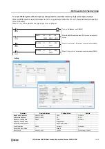
4. S2 (source 2): Initialization Input
S2 specifies the initialization input. When the initialization input S2 is turned on, the initial values configured in the WindLDR
PWM (Pulse Width Modulation)
dialog box, on the
Settings
tab, are stored in the control registers. An external input or an
internal relay can be specified.
When the initialization input is on, the initial values are written to the data registers with each scan. To only initialize the values
one time, use the initialization input in combination with the SOTU (single output up) instruction or the SOTD (single output
down) instruction.
5. D1 (destination 1): Operation Status
D1 specifies the first internal relay of the internal relays to use with PWM instructions.
Starting from the specified internal relay, 3 sequential internal relays are used.
Specify the first internal relay so that the device range is not exceeded.
Instruction
Pulse Output
Configurable Range
Frequency
Duty Cycle
PWM1
15 Hz to 5 kHz (increments of 1 Hz)
0.1 to 100.0 (increments of 0.1%)
PWM2
PWM3
PWM4
Storage
Destination
Function
Setting
Reference
Starting 0
Output pulse frequency
15 to 5,000 (increments of 1 Hz)
"6. Output pulse frequency" on page 18-11
Starting 1
Pulse duty cycle (ON ratio)
1 to 1,000 (increments of 0.1%)
"7. Pulse width ratio" on page 18-11
1 to 100 (increments of 1%)
Starting 2
Preset value (high word)
1 to 100,000,000 pulses
"9. Preset value" on page 18-11
Starting 3
Preset value (low word)
Starting 4
Current value (high word)
1 to 100,000,000 pulses
"10. Current value" on page 18-11
Starting 5
Current value (low word)
Starting 6
Error status
0 to 4
"11. Error status" on page 18-11
Starting 7
Reserved
Storage Destination
Function
Setting
Starting 0
Pulse output ON
0: Pulse output OFF
1: Pulse output ON
This relay turns on during pulse output.
This relay turns off when pulse output stops.
This relay turns off when the specified number of pulses
are output and output ends.
Starting 1
Pulse output
complete
0: Pulse output not complete
1: Pulse output complete
This relay turns on when pulse output is complete.
This relay turns off when pulse output stops.
Starting 2
Overflow
0: None
1: An overflow has occurred
When pulse counting is enabled, this relay turns on when
a pulse is output that exceeds the configured preset value.
Содержание MICROSmart FC6A Series
Страница 1: ...B 1726 7 FC6A SERIES Ladder Programming Manual ...
Страница 8: ...Preface 7 FC6A SERIES MICROSMART LADDER PROGRAMMING MANUAL FC9Y B1726 ...
Страница 32: ...1 OPERATION BASICS 1 20 FC6A SERIES MICROSMART LADDER PROGRAMMING MANUAL FC9Y B1726 ...
Страница 96: ...3 INSTRUCTIONS REFERENCE 3 18 FC6A SERIES MICROSMART LADDER PROGRAMMING MANUAL FC9Y B1726 ...
Страница 130: ...4 BASIC INSTRUCTIONS 4 34 FC6A SERIES MICROSMART LADDER PROGRAMMING MANUAL FC9Y B1726 ...
Страница 158: ...6 DATA COMPARISON INSTRUCTIONS 6 10 FC6A SERIES MICROSMART LADDER PROGRAMMING MANUAL FC9Y B1726 ...
Страница 192: ...9 SHIFT ROTATE INSTRUCTIONS 9 12 FC6A SERIES MICROSMART LADDER PROGRAMMING MANUAL FC9Y B1726 ...
Страница 216: ...10 DATA CONVERSION INSTRUCTIONS 10 24 FC6A SERIES MICROSMART LADDER PROGRAMMING MANUAL FC9Y B1726 ...
Страница 248: ...11 WEEK PROGRAMMER INSTRUCTIONS 11 32 FC6A SERIES MICROSMART LADDER PROGRAMMING MANUAL FC9Y B1726 ...
Страница 272: ...12 DISPLAY INSTRUCTIONS 12 24 FC6A SERIES MICROSMART LADDER PROGRAMMING MANUAL FC9Y B1726 ...
Страница 284: ...14 REFRESH INSTRUCTIONS 14 6 FC6A SERIES MICROSMART LADDER PROGRAMMING MANUAL FC9Y B1726 ...
Страница 288: ...15 INTERRUPT CONTROL INSTRUCTIONS 15 4 FC6A SERIES MICROSMART LADDER PROGRAMMING MANUAL FC9Y B1726 ...
Страница 294: ...16 COORDINATE CONVERSION INSTRUCTIONS 16 6 FC6A SERIES MICROSMART LADDER PROGRAMMING MANUAL FC9Y B1726 ...
Страница 374: ...18 PULSE OUTPUT INSTRUCTIONS 18 78 FC6A SERIES MICROSMART LADDER PROGRAMMING MANUAL FC9Y B1726 Setting ...
Страница 450: ...20 DUAL TEACHING TIMER INSTRUCTIONS 20 4 FC6A SERIES MICROSMART LADDER PROGRAMMING MANUAL FC9Y B1726 ...
Страница 502: ...25 DATA LOG INSTRUCTIONS 25 22 FC6A SERIES MICROSMART LADDER PROGRAMMING MANUAL FC9Y B1726 ...
Страница 546: ...26 SCRIPT 26 44 FC6A SERIES MICROSMART LADDER PROGRAMMING MANUAL FC9Y B1726 ...
Страница 574: ...27 FLOW CALCULATION INSTRUCTIONS 27 28 FC6A SERIES MICROSMART LADDER PROGRAMMING MANUAL FC9Y B1726 ...
Страница 583: ...FC6A SERIES MICROSMART LADDER PROGRAMMING MANUAL FC9Y B1726 28 9 28 USER DEFINED MACRO INSTRUCTION ...
Страница 584: ...28 USER DEFINED MACRO INSTRUCTION 28 10 FC6A SERIES MICROSMART LADDER PROGRAMMING MANUAL FC9Y B1726 ...
Страница 598: ...APPENDIX A 14 FC6A SERIES MICROSMART LADDER PROGRAMMING MANUAL FC9Y B1726 ...


