


19: PID C
ONTROL
I
NSTRUCTION
19-16
FC6A S
ERIES
MICROS
MART
L
ADDER
P
ROGRAMMING
M
ANUAL
FC9Y-B1726
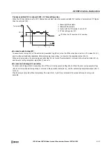
This function is suitable for the control of high-temperature heaters (elements composed of molybdenum, tungsten, platinum,
used at approximately 1,500 to 1,800°C) that burn out when rapidly energized.
11. Proportional Band Offset (S1+20)
Sets the offset for the proportional band. The output manipulated variable (S1+1) can be increased or decreased by the value
set as the proportional band offset.
For example, if the proportional band offset is set to 20%, the output manipulated variable (S1+1) is increased by 20%.
The proportional band offset can be set from -100 to 100%.
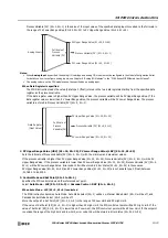
12. Control Period (S1+21)
Set the cycle to perform on/off control of the control (S3+5) output according to the output manipulated variable. The on pulse
width for the control period varies according to the output manipulated variable.
The control period can be set from 0.1 to 50.0 seconds in 0.1 second increments.
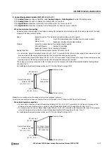
When control period: 5 seconds (set value 50)
13. Advanced/Basic
Click this button and you can show or hide the advanced settings. On the
Output
tab, Output Manipulated Variable Limit (6),
Output Manipulated Variable Upper Limit/Percentage (7), Output Manipulated Variable Lower Limit (8), Manual Mode Output MV
(9), Output MV Rate-of-Change (10), Proportional Band Offset (11), and Control Period (12) can be set as advanced settings.
S1: Control Registers
Storage
Destination
Function
Setting Details
R/W
S1+0
Process variable
• When
Analog Input
is specified
R/W
AI0 to AI5 can be selected. S1+0 is read-only.
• When
Data Register
is specified
Store a value that satisfies process variable minimum value
≤
process
variable
≤
process variable maximum value. S1+0 is readable/writable.
S1+1
Output manipulated variable
Store a value between 0 and 100 (0% to 100%).
R
S1+2
Operation status
Store the PIDA instruction execution status or error status.
For details, see "Operation status (S1+2)" on page 19-19.
R
S1+3
Alarm 1 (process high alarm)
Set a value that satisfies alarm 2 value (process low alarm) < alarm 1 value
≤
process variable maximum.
Operates as process variable maximum value when alarm 1 value
≤
alarm 2
value (process low alarm) or alarm 1 value > process variable maximum value.
R/W
S1+4
Alarm 2 (process low alarm)
Set a value that satisfies process variable minimum value
≤
alarm 2 value <
alarm 1 value (process high alarm)
Operates as process variable minimum value when alarm 2 value < process
value minimum value or alarm 1 value (process high alarm)
≤
alarm 2 value.
R/W
S1+5
Sampling period
Set a value between 1 and 10,000 (0.01 to 100.00 seconds).
Sampling period of 0 operates as 0.01 seconds and 10,001 or higher operates
as 100.00 seconds.
R/W
S1+6
Control mode
Select the control mode.
0: PID control
1: Proportional control
2: PI control
3: PD control
Operates as 0 (PID Control) when a value other than those listed above.
R/W
S1+7
Set point
Set a value that satisfies process variable minimum value
≤
set point
≤
process variable maximum value.
When set point < process variable minimum value or process variable
maximum value < set point, a set point configuration error occurs and the
previous set point is retained.
R/W
S1+8
Proportional band
Set a value between 1 and 10,000 (±0.01 to ±100.00%)
Proportional band of 0 operates as ±0.01% and 10,001 or higher operates as
±100.00%.
R/W
OFF
OFF
OFF
OFF
ON (4 s)
ON (3 s)
ON (2.5 s)
Output manipulated
variable (80%)
Output manipulated
variable (60%)
Output manipulated
variable (50%)
ON
Control output
5 s
5 s
5 s
Содержание MICROSmart FC6A Series
Страница 1: ...B 1726 7 FC6A SERIES Ladder Programming Manual ...
Страница 8: ...Preface 7 FC6A SERIES MICROSMART LADDER PROGRAMMING MANUAL FC9Y B1726 ...
Страница 32: ...1 OPERATION BASICS 1 20 FC6A SERIES MICROSMART LADDER PROGRAMMING MANUAL FC9Y B1726 ...
Страница 96: ...3 INSTRUCTIONS REFERENCE 3 18 FC6A SERIES MICROSMART LADDER PROGRAMMING MANUAL FC9Y B1726 ...
Страница 130: ...4 BASIC INSTRUCTIONS 4 34 FC6A SERIES MICROSMART LADDER PROGRAMMING MANUAL FC9Y B1726 ...
Страница 158: ...6 DATA COMPARISON INSTRUCTIONS 6 10 FC6A SERIES MICROSMART LADDER PROGRAMMING MANUAL FC9Y B1726 ...
Страница 192: ...9 SHIFT ROTATE INSTRUCTIONS 9 12 FC6A SERIES MICROSMART LADDER PROGRAMMING MANUAL FC9Y B1726 ...
Страница 216: ...10 DATA CONVERSION INSTRUCTIONS 10 24 FC6A SERIES MICROSMART LADDER PROGRAMMING MANUAL FC9Y B1726 ...
Страница 248: ...11 WEEK PROGRAMMER INSTRUCTIONS 11 32 FC6A SERIES MICROSMART LADDER PROGRAMMING MANUAL FC9Y B1726 ...
Страница 272: ...12 DISPLAY INSTRUCTIONS 12 24 FC6A SERIES MICROSMART LADDER PROGRAMMING MANUAL FC9Y B1726 ...
Страница 284: ...14 REFRESH INSTRUCTIONS 14 6 FC6A SERIES MICROSMART LADDER PROGRAMMING MANUAL FC9Y B1726 ...
Страница 288: ...15 INTERRUPT CONTROL INSTRUCTIONS 15 4 FC6A SERIES MICROSMART LADDER PROGRAMMING MANUAL FC9Y B1726 ...
Страница 294: ...16 COORDINATE CONVERSION INSTRUCTIONS 16 6 FC6A SERIES MICROSMART LADDER PROGRAMMING MANUAL FC9Y B1726 ...
Страница 374: ...18 PULSE OUTPUT INSTRUCTIONS 18 78 FC6A SERIES MICROSMART LADDER PROGRAMMING MANUAL FC9Y B1726 Setting ...
Страница 450: ...20 DUAL TEACHING TIMER INSTRUCTIONS 20 4 FC6A SERIES MICROSMART LADDER PROGRAMMING MANUAL FC9Y B1726 ...
Страница 502: ...25 DATA LOG INSTRUCTIONS 25 22 FC6A SERIES MICROSMART LADDER PROGRAMMING MANUAL FC9Y B1726 ...
Страница 546: ...26 SCRIPT 26 44 FC6A SERIES MICROSMART LADDER PROGRAMMING MANUAL FC9Y B1726 ...
Страница 574: ...27 FLOW CALCULATION INSTRUCTIONS 27 28 FC6A SERIES MICROSMART LADDER PROGRAMMING MANUAL FC9Y B1726 ...
Страница 583: ...FC6A SERIES MICROSMART LADDER PROGRAMMING MANUAL FC9Y B1726 28 9 28 USER DEFINED MACRO INSTRUCTION ...
Страница 584: ...28 USER DEFINED MACRO INSTRUCTION 28 10 FC6A SERIES MICROSMART LADDER PROGRAMMING MANUAL FC9Y B1726 ...
Страница 598: ...APPENDIX A 14 FC6A SERIES MICROSMART LADDER PROGRAMMING MANUAL FC9Y B1726 ...


