


FC6A S
ERIES
MICROS
MART
L
ADDER
P
ROGRAMMING
M
ANUAL
FC9Y-B1726
19-33
19: PID C
ONTROL
I
NSTRUCTION
■
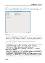
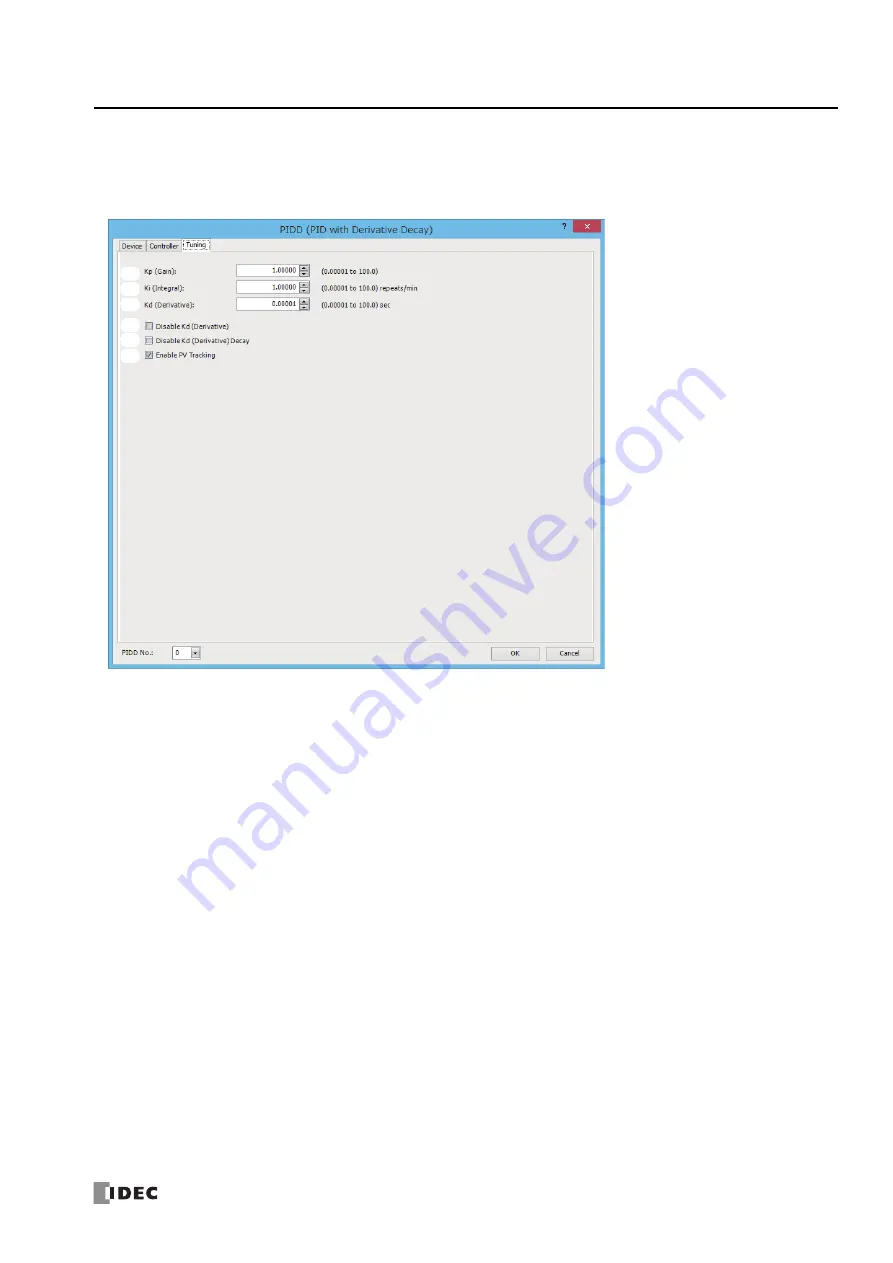
Tuning tab
This tab is used to configure the tuning parameters of the PIDD instruction.
To store the initial values of the PIDD instruction that are set on the
Tuning
tab in the control registers and control relays, turn on the
initialization input for the corresponding PIDD instruction after the user program is downloaded to the FC6A Series MICROSmart.
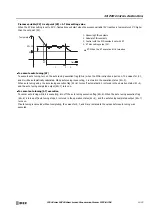
1. Kp (Gain) (S1+6, S1+7)
Sets the proportional gain for PID control. The proportional action changes the output in proportion to the difference (called the
offset) between the set point (SP) and the process variable (PV). If the process variable is within the range of the proportional
band, the output manipulated variable proportional to the deviation is output.
When the proportional gain is made smaller, overshooting (process variable goes above the set point), undershooting (process
variable falls below the set point), and hunting (process variable is in an unstable undulating state) decrease, but it takes time
until the process variable reaches the set point and the offset between the set point and the process variable becomes larger.
When proportional gain is made larger, the time until the process variable reaches the set point decreases and the offset
becomes smaller, but hunting increases.
Kp (Gain) (S1+6, S1+7) is set as data type F (float) between 0.00001 and 100.0 (0.00001 and 100.0%).
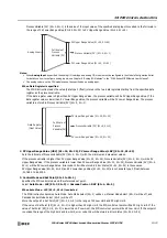
2. Ki (Integral) (S1+8, S1+9)
Sets the integral gain for PID control. Integral gain is the factor that determines the output manipulated variable by the integral
action. With only the proportional action, an offset occurs between the set point and the process variable even when the subject
to control has reached a stable state. In order to bring this offset close to 0, the integral action is required.
When integral gain is increased, the integral action becomes stronger and the set point is quickly reached, but this causes
hunting with a long cycle. When integral gain is decreased, it will take time to reach the set point.
Ki (Integral) (S1+8, S1+9) is set as data type F (float) between 0.00001 and 100.0 (0.00001 and 100.0 times/minute).
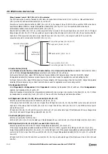
3. Kd (Derivative) (S1+10, S1+11)
Sets the derivative gain for PID control. Derivative gain is the factor that determines the output manipulated variable by the
derivative action. The derivative action changes the output manipulated variable and rapidly stabilizes the process variable when
there is a change in the process variable due to a factor such as an external disturbance.
When derivative gain is decreased, the derivative action becomes weaker and the response to rapid process variable changes
becomes slower. When derivative gain is increased, the derivative action becomes stronger and the response to rapid changes in
the process variable becomes faster, but the control becomes sensitive to changes in the process variable and changes in the
output manipulated variable will become more severe.
Kd (Derivative) (S1+10, S1+11) is set as data type F (float) between 0.00001 and 100.0 (0.00001 and 100.0 seconds).
1.
2.
3.
4.
5.
6.
Содержание MICROSmart FC6A Series
Страница 1: ...B 1726 7 FC6A SERIES Ladder Programming Manual ...
Страница 8: ...Preface 7 FC6A SERIES MICROSMART LADDER PROGRAMMING MANUAL FC9Y B1726 ...
Страница 32: ...1 OPERATION BASICS 1 20 FC6A SERIES MICROSMART LADDER PROGRAMMING MANUAL FC9Y B1726 ...
Страница 96: ...3 INSTRUCTIONS REFERENCE 3 18 FC6A SERIES MICROSMART LADDER PROGRAMMING MANUAL FC9Y B1726 ...
Страница 130: ...4 BASIC INSTRUCTIONS 4 34 FC6A SERIES MICROSMART LADDER PROGRAMMING MANUAL FC9Y B1726 ...
Страница 158: ...6 DATA COMPARISON INSTRUCTIONS 6 10 FC6A SERIES MICROSMART LADDER PROGRAMMING MANUAL FC9Y B1726 ...
Страница 192: ...9 SHIFT ROTATE INSTRUCTIONS 9 12 FC6A SERIES MICROSMART LADDER PROGRAMMING MANUAL FC9Y B1726 ...
Страница 216: ...10 DATA CONVERSION INSTRUCTIONS 10 24 FC6A SERIES MICROSMART LADDER PROGRAMMING MANUAL FC9Y B1726 ...
Страница 248: ...11 WEEK PROGRAMMER INSTRUCTIONS 11 32 FC6A SERIES MICROSMART LADDER PROGRAMMING MANUAL FC9Y B1726 ...
Страница 272: ...12 DISPLAY INSTRUCTIONS 12 24 FC6A SERIES MICROSMART LADDER PROGRAMMING MANUAL FC9Y B1726 ...
Страница 284: ...14 REFRESH INSTRUCTIONS 14 6 FC6A SERIES MICROSMART LADDER PROGRAMMING MANUAL FC9Y B1726 ...
Страница 288: ...15 INTERRUPT CONTROL INSTRUCTIONS 15 4 FC6A SERIES MICROSMART LADDER PROGRAMMING MANUAL FC9Y B1726 ...
Страница 294: ...16 COORDINATE CONVERSION INSTRUCTIONS 16 6 FC6A SERIES MICROSMART LADDER PROGRAMMING MANUAL FC9Y B1726 ...
Страница 374: ...18 PULSE OUTPUT INSTRUCTIONS 18 78 FC6A SERIES MICROSMART LADDER PROGRAMMING MANUAL FC9Y B1726 Setting ...
Страница 450: ...20 DUAL TEACHING TIMER INSTRUCTIONS 20 4 FC6A SERIES MICROSMART LADDER PROGRAMMING MANUAL FC9Y B1726 ...
Страница 502: ...25 DATA LOG INSTRUCTIONS 25 22 FC6A SERIES MICROSMART LADDER PROGRAMMING MANUAL FC9Y B1726 ...
Страница 546: ...26 SCRIPT 26 44 FC6A SERIES MICROSMART LADDER PROGRAMMING MANUAL FC9Y B1726 ...
Страница 574: ...27 FLOW CALCULATION INSTRUCTIONS 27 28 FC6A SERIES MICROSMART LADDER PROGRAMMING MANUAL FC9Y B1726 ...
Страница 583: ...FC6A SERIES MICROSMART LADDER PROGRAMMING MANUAL FC9Y B1726 28 9 28 USER DEFINED MACRO INSTRUCTION ...
Страница 584: ...28 USER DEFINED MACRO INSTRUCTION 28 10 FC6A SERIES MICROSMART LADDER PROGRAMMING MANUAL FC9Y B1726 ...
Страница 598: ...APPENDIX A 14 FC6A SERIES MICROSMART LADDER PROGRAMMING MANUAL FC9Y B1726 ...


