


6: D
ATA
C
OMPARISON
I
NSTRUCTIONS
6-2
FC6A S
ERIES
MICROS
MART
L
ADDER
P
ROGRAMMING
M
ANUAL
FC9Y-B1726
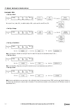
Valid Devices
For valid device address ranges, see "Device Addresses" on page 2-1.
When only S1 and/or S2 is repeated, the logical operation type can be selected from AND or OR.
Special internal relays cannot be designated as D1.
When T (timer) or C (counter) is used as S1 or S2, the timer/counter current value (TC or CC) is displayed.
When F (float) data is selected, only data register and constant can be designated as S1 and S2.
When F (float) data is selected and S1 or S2 does not comply with the normal floating-point format, a user program execution error will result,
turning on special internal relay M8004 and ERR LED on the FC6A Series MICROSmart. For user program execution errors, see "User Program
Execution Errors" on page 3-10.
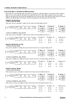
Valid Data Types
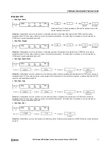
Special Internal Relays M8150, M8151, and M8152 in CMP=
Three special internal relays are available to indicate the comparison result of the CMP= instruction. Depending on the result, one
of the three special internal relays turns on.
When more than one CMP= or ICMP>= instruction is used, M8150, M8151, or M8152 indicates the result of the instruction that
was executed last.
Device
Function
I
Q
M
R
T
C
D
P
Constant
Repeat
Repeat Result
Logical AND or OR operation
—
—
—
—
—
—
—
—
—
—
S1 (Source 1)
Data to compare
X
X
X
X
X
X
X
—
X
1-99
S2 (Source 2)
Data to compare
X
X
X
X
X
X
X
—
X
1-99
D1 (Destination 1)
Comparison output
—
X
—
—
—
—
—
—
1-99
W (word)
X
When a bit device such as I (input), Q (output), M (internal relay), or R (shift register) is assigned as the source,
16 points (word or integer data) or 32 points (double-word or long data) are used. When repeat is assigned for a
bit device, the quantity of device bits increases in 16- or 32-point increments.
When a word device such as T (timer), C (counter), or D (data register) is assigned as the source, 1 point (word
or integer data) or 2 points (double-word, long, or float data) are used. When repeat is assigned for a word
device, the quantity of device words increases in 1- or 2-point increments.
When an output or internal relay is assigned as the destination, only 1 point is used regardless of the selected
data type. When repeat is assigned for the destination, outputs or internal relays as many as the repeat cycles
are used.
I (integer)
X
D (double word)
X
L (long)
X
F (float)
X
When S1 > S2, M8150 turns on.
When S1 = S2, M8151 turns on.
When S1 < S2, M8152 turns on.
S2
S1
(2)
(1)
(3)
Small
Large
When repeat is designated, the comparison result of the last repeat cycle
turns on one of the three special internal relays.
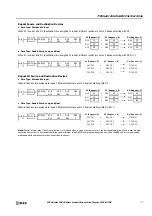
S2 Value
M8150
M8151
M8152
D1
Status
(1) S1 > S2
ON
OFF
OFF
OFF
(2) S1 = S2
OFF
ON
OFF
ON
(3) S1 < S2
OFF
OFF
ON
OFF
Содержание MICROSmart FC6A Series
Страница 1: ...B 1726 7 FC6A SERIES Ladder Programming Manual ...
Страница 8: ...Preface 7 FC6A SERIES MICROSMART LADDER PROGRAMMING MANUAL FC9Y B1726 ...
Страница 32: ...1 OPERATION BASICS 1 20 FC6A SERIES MICROSMART LADDER PROGRAMMING MANUAL FC9Y B1726 ...
Страница 96: ...3 INSTRUCTIONS REFERENCE 3 18 FC6A SERIES MICROSMART LADDER PROGRAMMING MANUAL FC9Y B1726 ...
Страница 130: ...4 BASIC INSTRUCTIONS 4 34 FC6A SERIES MICROSMART LADDER PROGRAMMING MANUAL FC9Y B1726 ...
Страница 158: ...6 DATA COMPARISON INSTRUCTIONS 6 10 FC6A SERIES MICROSMART LADDER PROGRAMMING MANUAL FC9Y B1726 ...
Страница 192: ...9 SHIFT ROTATE INSTRUCTIONS 9 12 FC6A SERIES MICROSMART LADDER PROGRAMMING MANUAL FC9Y B1726 ...
Страница 216: ...10 DATA CONVERSION INSTRUCTIONS 10 24 FC6A SERIES MICROSMART LADDER PROGRAMMING MANUAL FC9Y B1726 ...
Страница 248: ...11 WEEK PROGRAMMER INSTRUCTIONS 11 32 FC6A SERIES MICROSMART LADDER PROGRAMMING MANUAL FC9Y B1726 ...
Страница 272: ...12 DISPLAY INSTRUCTIONS 12 24 FC6A SERIES MICROSMART LADDER PROGRAMMING MANUAL FC9Y B1726 ...
Страница 284: ...14 REFRESH INSTRUCTIONS 14 6 FC6A SERIES MICROSMART LADDER PROGRAMMING MANUAL FC9Y B1726 ...
Страница 288: ...15 INTERRUPT CONTROL INSTRUCTIONS 15 4 FC6A SERIES MICROSMART LADDER PROGRAMMING MANUAL FC9Y B1726 ...
Страница 294: ...16 COORDINATE CONVERSION INSTRUCTIONS 16 6 FC6A SERIES MICROSMART LADDER PROGRAMMING MANUAL FC9Y B1726 ...
Страница 374: ...18 PULSE OUTPUT INSTRUCTIONS 18 78 FC6A SERIES MICROSMART LADDER PROGRAMMING MANUAL FC9Y B1726 Setting ...
Страница 450: ...20 DUAL TEACHING TIMER INSTRUCTIONS 20 4 FC6A SERIES MICROSMART LADDER PROGRAMMING MANUAL FC9Y B1726 ...
Страница 502: ...25 DATA LOG INSTRUCTIONS 25 22 FC6A SERIES MICROSMART LADDER PROGRAMMING MANUAL FC9Y B1726 ...
Страница 546: ...26 SCRIPT 26 44 FC6A SERIES MICROSMART LADDER PROGRAMMING MANUAL FC9Y B1726 ...
Страница 574: ...27 FLOW CALCULATION INSTRUCTIONS 27 28 FC6A SERIES MICROSMART LADDER PROGRAMMING MANUAL FC9Y B1726 ...
Страница 583: ...FC6A SERIES MICROSMART LADDER PROGRAMMING MANUAL FC9Y B1726 28 9 28 USER DEFINED MACRO INSTRUCTION ...
Страница 584: ...28 USER DEFINED MACRO INSTRUCTION 28 10 FC6A SERIES MICROSMART LADDER PROGRAMMING MANUAL FC9Y B1726 ...
Страница 598: ...APPENDIX A 14 FC6A SERIES MICROSMART LADDER PROGRAMMING MANUAL FC9Y B1726 ...


