


19: PID C
ONTROL
I
NSTRUCTION
19-30
FC6A S
ERIES
MICROS
MART
L
ADDER
P
ROGRAMMING
M
ANUAL
FC9Y-B1726
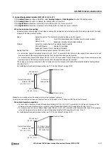
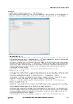
When Cascade Control - RSP (S1+4, S1+5) is selected
The PIDD instruction becomes Cascade Control Mode. Cascade Control Mode Select (S3+3) will be on, Manual Mode Select
(S3+1) will be off, and Auto Mode Select (S3+2) will be off.
Store the set point in Remote Set Point (RSP) (S1+4, S1+5) in the range of 0.0 and 100.0%. When another PIDD instruction is
specified as Master PIDD No., Output Manipulated Variable (MV) (S1+16, S1+17) of the specified PIDD instruction is
automatically loaded into Remote Set Point (RSP) (S1+4, S1+5).
Remote Set Point (RSP) (S1+4, S1+5) will be converted to the full scale of SP Lower Range Value (S1+44, S1+45) to SP Upper
Range Value (S1+46, S1+47). If the converted set point is higher than SP High Limit (S1+28, S1+29), the set point will be SP
High Limit. If the converted set point is lower than SP Low Limit (S1+26, S1+27), the set point will be SP Low Limit. The
converted set point is stored in Set Point (SP) (S1+2, S1+3).
4. Control Action (S3+0)
Select
Reverse Control Action
or
Direct Control Action
. When
Reverse Control Action
is selected, Control Action (S3+0)
will be off. When
Direct Control Action
is selected, Control Action (S3+0) will be on.
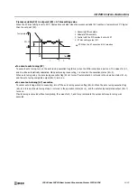
For Reverse Control Action, when PIDD instruction Process Variable (PV) becomes larger than Set Point (SP), Output
Manipulated Variable (MV) becomes smaller. Reverse Control Action is used for applications such as heating control.
For Direct Control Action, when PIDD instruction Process Variable (PV) becomes larger than Set Point (SP), Output Manipulated
Variable (MV) also becomes larger. Direct Control Action is used for applications such as cooling control.
5. Kp Dependent (S3+8)
Select
Dependent
or
Independent
. When
Dependent
is selected, Kp Dependent (S3+8) will be on. When
Independent
is
selected, Kp Dependent (S3+8) will be off.
When Kp Dependent is selected, the integral and derivative actions grow larger in proportion to Kp (Gain) (S1+6, S1+7). When
Kp Independent is selected, Kp (Gain) (S1+6, S1+7) has no effect on the integral and derivative actions.
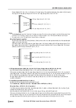
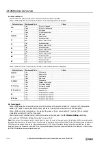
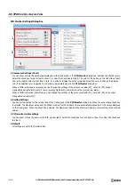
6. SP High Limit (S1+28, S1+29), SP Low Limit (S1+26, S1+27)
Sets the upper limit and lower limit of Set Point (SP) (S1+2, S1+3).
If the value of Set Point (SP) (S1+2, S1+3) is higher than SP High Limit (S1+28, S1+29), the PIDD control set point will be SP
High Limit. If the value of Set Point (SP) (S1+2, S1+3) is lower than SP Low Limit (S1+26, S1+27), the PIDD control set point
will be SP Low Limit.
SP High Limit (S1+28, S1+29) and SP Low Limit (S1+26, S1+27) are set as data type F (float) between SP Lower Range Value
(S1+44, S1+45) and SP Upper Range Value (S1+46, S1+47).
7. Set Point (SP) (S1+2, S1+3)
Sets the set point (SP) for PID control.
Set Point (SP) (S1+2, S1+3) is set as data type F (float) between SP Low Limit (S1+26, S1+27) and SP High Limit (S1+28, S1+29).
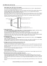
8. MV High Limit (S1+32, S1+33), MV Low Limit (S1+30, S1+31)
Sets the upper limit and lower limit of Output Manipulated Variable (MV) (S1+16, S1+17).
If the output manipulated variable calculated with PID control (0 to 100%) is greater than MV High Limit (S1+32, S1+33),
Output Manipulated Variable (MV) (S1+16, S1+17) will be MV High Limit. If the output manipulated variable calculated with PID
control (0 to 100%) is less than MV Low Limit (S1+30, S1+31), Output Manipulated Variable (MV) (S1+16, S1+17) will be MV
Low Limit.
MV High Limit (S1+32, S1+33) and MV Low Limit (S1+30, S1+31) are set as data type F (float) between 0.0 and 100.0 (0.0 and
100.0%).
SP High Limit (S1+28, S1+29)
SP Lower Range Value (S1+44, S1+45)
SP Low Limit (S1+26, S1+27)
Set Point (SP) (S1+2, S1+3)
0.0 to 100.0%
Full Scale of
Set Point (SP)
Remote Set Point (RSP)
(S1+4, S1+5)
SP Upper Range Value (S1+46, S1+47)
Содержание MICROSmart FC6A Series
Страница 1: ...B 1726 7 FC6A SERIES Ladder Programming Manual ...
Страница 8: ...Preface 7 FC6A SERIES MICROSMART LADDER PROGRAMMING MANUAL FC9Y B1726 ...
Страница 32: ...1 OPERATION BASICS 1 20 FC6A SERIES MICROSMART LADDER PROGRAMMING MANUAL FC9Y B1726 ...
Страница 96: ...3 INSTRUCTIONS REFERENCE 3 18 FC6A SERIES MICROSMART LADDER PROGRAMMING MANUAL FC9Y B1726 ...
Страница 130: ...4 BASIC INSTRUCTIONS 4 34 FC6A SERIES MICROSMART LADDER PROGRAMMING MANUAL FC9Y B1726 ...
Страница 158: ...6 DATA COMPARISON INSTRUCTIONS 6 10 FC6A SERIES MICROSMART LADDER PROGRAMMING MANUAL FC9Y B1726 ...
Страница 192: ...9 SHIFT ROTATE INSTRUCTIONS 9 12 FC6A SERIES MICROSMART LADDER PROGRAMMING MANUAL FC9Y B1726 ...
Страница 216: ...10 DATA CONVERSION INSTRUCTIONS 10 24 FC6A SERIES MICROSMART LADDER PROGRAMMING MANUAL FC9Y B1726 ...
Страница 248: ...11 WEEK PROGRAMMER INSTRUCTIONS 11 32 FC6A SERIES MICROSMART LADDER PROGRAMMING MANUAL FC9Y B1726 ...
Страница 272: ...12 DISPLAY INSTRUCTIONS 12 24 FC6A SERIES MICROSMART LADDER PROGRAMMING MANUAL FC9Y B1726 ...
Страница 284: ...14 REFRESH INSTRUCTIONS 14 6 FC6A SERIES MICROSMART LADDER PROGRAMMING MANUAL FC9Y B1726 ...
Страница 288: ...15 INTERRUPT CONTROL INSTRUCTIONS 15 4 FC6A SERIES MICROSMART LADDER PROGRAMMING MANUAL FC9Y B1726 ...
Страница 294: ...16 COORDINATE CONVERSION INSTRUCTIONS 16 6 FC6A SERIES MICROSMART LADDER PROGRAMMING MANUAL FC9Y B1726 ...
Страница 374: ...18 PULSE OUTPUT INSTRUCTIONS 18 78 FC6A SERIES MICROSMART LADDER PROGRAMMING MANUAL FC9Y B1726 Setting ...
Страница 450: ...20 DUAL TEACHING TIMER INSTRUCTIONS 20 4 FC6A SERIES MICROSMART LADDER PROGRAMMING MANUAL FC9Y B1726 ...
Страница 502: ...25 DATA LOG INSTRUCTIONS 25 22 FC6A SERIES MICROSMART LADDER PROGRAMMING MANUAL FC9Y B1726 ...
Страница 546: ...26 SCRIPT 26 44 FC6A SERIES MICROSMART LADDER PROGRAMMING MANUAL FC9Y B1726 ...
Страница 574: ...27 FLOW CALCULATION INSTRUCTIONS 27 28 FC6A SERIES MICROSMART LADDER PROGRAMMING MANUAL FC9Y B1726 ...
Страница 583: ...FC6A SERIES MICROSMART LADDER PROGRAMMING MANUAL FC9Y B1726 28 9 28 USER DEFINED MACRO INSTRUCTION ...
Страница 584: ...28 USER DEFINED MACRO INSTRUCTION 28 10 FC6A SERIES MICROSMART LADDER PROGRAMMING MANUAL FC9Y B1726 ...
Страница 598: ...APPENDIX A 14 FC6A SERIES MICROSMART LADDER PROGRAMMING MANUAL FC9Y B1726 ...


