


27: F
LOW
C
ALCULATION
I
NSTRUCTIONS
27-14
FC6A S
ERIES
MICROS
MART
L
ADDER
P
ROGRAMMING
M
ANUAL
FC9Y-B1726
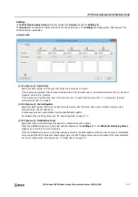
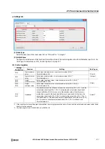
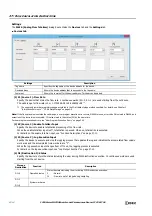
Settings
The
FLWA (Analog Flow Totalizer)
dialog box contains the
Devices
tab and the
Settings
tab.
■
Devices tab
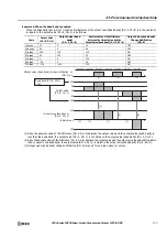
(1) S1 (Source 1): Flow Rate
Specify the device that stores the flow rate. 2 continuous words (S1+0, S1+1) are used starting from the set device.
The valid range for flow rate is 0 or 1.175494E-38 to 3.38
Note:
If the flow rate value is outside the valid range, a user program execution error occurs, M8004 turns on, error code 28 is stored in D8006, and
execution of the instruction is canceled. 10 is also stored in the status (D1) at the same time.
For user program execution errors, see "User Program Execution Errors" on page 3-10.
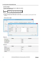
(2) S2 (Source 2): Enable Totalizer Input
Specify the device to enable totalization processing of the flow rate.
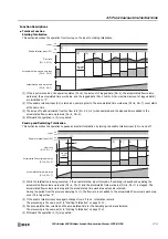
When the enable totalizer input is off, totalization is paused. When on, totalization is executed.
For details on the enable totalizer input, see "Function Descriptions" on page 27-11.
(3) S3 (Source 3): Log Execution Input
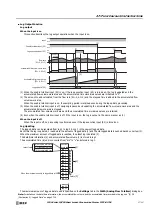
Specify the device to execute and stop the logging process that updates the log and initializes the accumulated flow volume
work area and the accumulated time work area to "0".
When the log execution input changes from off to on, the logging process is executed.
For details on the log execution input, see "Log Output Function" on page 27-13.
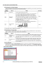
(4) D1 (Destination 1): Status
Specify the device to store the status including the error during FLWA instruction execution. 10 continuous words are used
starting from the set device.
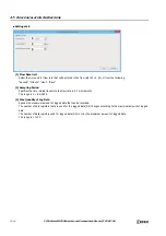
Settings
Description
Tag name
Specifies the tag name or the device address for the device.
Device address
Shows the device address that corresponds to the tag name.
Comment
Shows the comment for the device address. This item can be edited.
*1 The upper and lower data registers change according to the 32-bit data storage method specified. For details, see Chapter 3
"Instructions Reference" - "32-bit Data Storage" on page 3-9.
Storage
Destination
Function
Description
D1+0
Operation status
Stores the status including the error during FLWA instruction execution.
0
10
: Normal
: Flow rate
out of range during sampling
D1+1
D1+9
System work area
(1)
(2)
(3)
(4)
(5)
…
Содержание MICROSmart FC6A Series
Страница 1: ...B 1726 7 FC6A SERIES Ladder Programming Manual ...
Страница 8: ...Preface 7 FC6A SERIES MICROSMART LADDER PROGRAMMING MANUAL FC9Y B1726 ...
Страница 32: ...1 OPERATION BASICS 1 20 FC6A SERIES MICROSMART LADDER PROGRAMMING MANUAL FC9Y B1726 ...
Страница 96: ...3 INSTRUCTIONS REFERENCE 3 18 FC6A SERIES MICROSMART LADDER PROGRAMMING MANUAL FC9Y B1726 ...
Страница 130: ...4 BASIC INSTRUCTIONS 4 34 FC6A SERIES MICROSMART LADDER PROGRAMMING MANUAL FC9Y B1726 ...
Страница 158: ...6 DATA COMPARISON INSTRUCTIONS 6 10 FC6A SERIES MICROSMART LADDER PROGRAMMING MANUAL FC9Y B1726 ...
Страница 192: ...9 SHIFT ROTATE INSTRUCTIONS 9 12 FC6A SERIES MICROSMART LADDER PROGRAMMING MANUAL FC9Y B1726 ...
Страница 216: ...10 DATA CONVERSION INSTRUCTIONS 10 24 FC6A SERIES MICROSMART LADDER PROGRAMMING MANUAL FC9Y B1726 ...
Страница 248: ...11 WEEK PROGRAMMER INSTRUCTIONS 11 32 FC6A SERIES MICROSMART LADDER PROGRAMMING MANUAL FC9Y B1726 ...
Страница 272: ...12 DISPLAY INSTRUCTIONS 12 24 FC6A SERIES MICROSMART LADDER PROGRAMMING MANUAL FC9Y B1726 ...
Страница 284: ...14 REFRESH INSTRUCTIONS 14 6 FC6A SERIES MICROSMART LADDER PROGRAMMING MANUAL FC9Y B1726 ...
Страница 288: ...15 INTERRUPT CONTROL INSTRUCTIONS 15 4 FC6A SERIES MICROSMART LADDER PROGRAMMING MANUAL FC9Y B1726 ...
Страница 294: ...16 COORDINATE CONVERSION INSTRUCTIONS 16 6 FC6A SERIES MICROSMART LADDER PROGRAMMING MANUAL FC9Y B1726 ...
Страница 374: ...18 PULSE OUTPUT INSTRUCTIONS 18 78 FC6A SERIES MICROSMART LADDER PROGRAMMING MANUAL FC9Y B1726 Setting ...
Страница 450: ...20 DUAL TEACHING TIMER INSTRUCTIONS 20 4 FC6A SERIES MICROSMART LADDER PROGRAMMING MANUAL FC9Y B1726 ...
Страница 502: ...25 DATA LOG INSTRUCTIONS 25 22 FC6A SERIES MICROSMART LADDER PROGRAMMING MANUAL FC9Y B1726 ...
Страница 546: ...26 SCRIPT 26 44 FC6A SERIES MICROSMART LADDER PROGRAMMING MANUAL FC9Y B1726 ...
Страница 574: ...27 FLOW CALCULATION INSTRUCTIONS 27 28 FC6A SERIES MICROSMART LADDER PROGRAMMING MANUAL FC9Y B1726 ...
Страница 583: ...FC6A SERIES MICROSMART LADDER PROGRAMMING MANUAL FC9Y B1726 28 9 28 USER DEFINED MACRO INSTRUCTION ...
Страница 584: ...28 USER DEFINED MACRO INSTRUCTION 28 10 FC6A SERIES MICROSMART LADDER PROGRAMMING MANUAL FC9Y B1726 ...
Страница 598: ...APPENDIX A 14 FC6A SERIES MICROSMART LADDER PROGRAMMING MANUAL FC9Y B1726 ...


