


FC6A S
ERIES
MICROS
MART
L
ADDER
P
ROGRAMMING
M
ANUAL
FC9Y-B1726
18-75
18: P
ULSE
O
UTPUT
I
NSTRUCTIONS
■
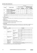
Settings tab
6. Steady pulse frequency
This setting specifies the steady pulse frequency after the pulse frequency is increased. Set between 15 and 100 kHz in 1 Hz
increments. The output frequency error is within ±5%.
For JOG3 and JOG4 with the All-in-One CPU module, set between 15 and 5 kHz in 1 Hz increments.
7. Initial pulse frequency
Specifies the frequency when pulse output starts. Set between 15 and 100 kHz in 1 Hz increments. The output frequency error
is within ±5%.
For JOG3 and JOG4 with the All-in-One CPU module, set between 15 and 5 kHz in 1 Hz increments.
8. Acceleration time
Specifies the time to increase the pulse frequency. Set the value in the range of 10 to 10,000 ms in increments of 1 ms. The first
digit of the setting is handled as zero. For example, if 144 is entered, the set value is handled as 140 ms.
9. Deceleration time
This setting specifies the time to decrease the pulse frequency. Set the value in the range of 10 to 10,000 ms in increments of
1 ms. The first digit of the setting is handled as zero. For example, if 144 is entered, the set value is handled as 140 ms.
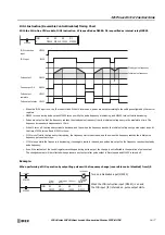
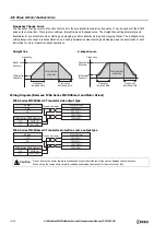
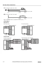
10. Reversible control enable
This setting enables or disables reversible control and selects the reversible control method from the following reversible control
modes. There are two modes for the pulse output mode: single-pulse output mode and dual-pulse output mode. They can be
combined with reversible control as follows. (This is an example when JOG1 is used with the All-in-One CPU module.)
The used outputs differ by the instruction used, the combination of the pulse output mode and reversible control, and the model
used.
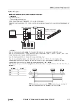
Reversible Control Enable
Operation
Pattern
Reversible control disabled
Select this option when using pulse output in a single
direction. Pulse A and pulse B can be used independently.
Reversible control
Single-pulse
output
Pulse A is used as pulse output. Pulse B on/off is used as
reversible control.
Reversible control
Dual-pulse output
Pulse A is used as forward pulse (CW) output.Pulse B is
used as reverse pulse (CCW) output.
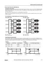
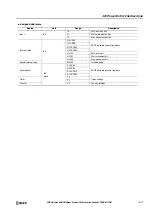
Command
Operating Condition
Output Used
All-in-One CPU Module
CAN J1939 All-in-One CPU
Module/Plus CPU Module
Pulse Output
Reversible
Control Output
Pulse Output
Reversible
Control Output
JOG1
Reversible control disabled
Q0
—
Q0
—
Reversible control
Single-pulse output
Q0
Q2
Q0
Q1
Reversible control
Dual-pulse output
Q0, Q1
—
Q0, Q1
—
JOG2
Reversible control disabled
Q1
—
Q2
—
Reversible control
Single-pulse output
Q1
Q3
Q2
Q3
Reversible control
Dual-pulse output
—
—
Q2, Q3
—
9.
8.
7.
6.
10.
11.
12.
13.
Q0
Q0
Q2
Q0
Q1
Содержание MICROSmart FC6A Series
Страница 1: ...B 1726 7 FC6A SERIES Ladder Programming Manual ...
Страница 8: ...Preface 7 FC6A SERIES MICROSMART LADDER PROGRAMMING MANUAL FC9Y B1726 ...
Страница 32: ...1 OPERATION BASICS 1 20 FC6A SERIES MICROSMART LADDER PROGRAMMING MANUAL FC9Y B1726 ...
Страница 96: ...3 INSTRUCTIONS REFERENCE 3 18 FC6A SERIES MICROSMART LADDER PROGRAMMING MANUAL FC9Y B1726 ...
Страница 130: ...4 BASIC INSTRUCTIONS 4 34 FC6A SERIES MICROSMART LADDER PROGRAMMING MANUAL FC9Y B1726 ...
Страница 158: ...6 DATA COMPARISON INSTRUCTIONS 6 10 FC6A SERIES MICROSMART LADDER PROGRAMMING MANUAL FC9Y B1726 ...
Страница 192: ...9 SHIFT ROTATE INSTRUCTIONS 9 12 FC6A SERIES MICROSMART LADDER PROGRAMMING MANUAL FC9Y B1726 ...
Страница 216: ...10 DATA CONVERSION INSTRUCTIONS 10 24 FC6A SERIES MICROSMART LADDER PROGRAMMING MANUAL FC9Y B1726 ...
Страница 248: ...11 WEEK PROGRAMMER INSTRUCTIONS 11 32 FC6A SERIES MICROSMART LADDER PROGRAMMING MANUAL FC9Y B1726 ...
Страница 272: ...12 DISPLAY INSTRUCTIONS 12 24 FC6A SERIES MICROSMART LADDER PROGRAMMING MANUAL FC9Y B1726 ...
Страница 284: ...14 REFRESH INSTRUCTIONS 14 6 FC6A SERIES MICROSMART LADDER PROGRAMMING MANUAL FC9Y B1726 ...
Страница 288: ...15 INTERRUPT CONTROL INSTRUCTIONS 15 4 FC6A SERIES MICROSMART LADDER PROGRAMMING MANUAL FC9Y B1726 ...
Страница 294: ...16 COORDINATE CONVERSION INSTRUCTIONS 16 6 FC6A SERIES MICROSMART LADDER PROGRAMMING MANUAL FC9Y B1726 ...
Страница 374: ...18 PULSE OUTPUT INSTRUCTIONS 18 78 FC6A SERIES MICROSMART LADDER PROGRAMMING MANUAL FC9Y B1726 Setting ...
Страница 450: ...20 DUAL TEACHING TIMER INSTRUCTIONS 20 4 FC6A SERIES MICROSMART LADDER PROGRAMMING MANUAL FC9Y B1726 ...
Страница 502: ...25 DATA LOG INSTRUCTIONS 25 22 FC6A SERIES MICROSMART LADDER PROGRAMMING MANUAL FC9Y B1726 ...
Страница 546: ...26 SCRIPT 26 44 FC6A SERIES MICROSMART LADDER PROGRAMMING MANUAL FC9Y B1726 ...
Страница 574: ...27 FLOW CALCULATION INSTRUCTIONS 27 28 FC6A SERIES MICROSMART LADDER PROGRAMMING MANUAL FC9Y B1726 ...
Страница 583: ...FC6A SERIES MICROSMART LADDER PROGRAMMING MANUAL FC9Y B1726 28 9 28 USER DEFINED MACRO INSTRUCTION ...
Страница 584: ...28 USER DEFINED MACRO INSTRUCTION 28 10 FC6A SERIES MICROSMART LADDER PROGRAMMING MANUAL FC9Y B1726 ...
Страница 598: ...APPENDIX A 14 FC6A SERIES MICROSMART LADDER PROGRAMMING MANUAL FC9Y B1726 ...


