


4: B
ASIC
I
NSTRUCTIONS
4-18
FC6A S
ERIES
MICROS
MART
L
ADDER
P
ROGRAMMING
M
ANUAL
FC9Y-B1726
CUDD (Double-Word Up/Down Selection Reversible Counter)
The double-word up/down selection reversible counter CUDD has a selection input to switch the up/down gate, so the three inputs
are required. The circuit for a double-word up/down selection reversible counter must be programmed in the following order:
preset input, pulse input, up/down selection input, the CUDD instruction, and a counter number C0 through C510, followed by a
counter preset value from 0 to 4,294,967,295.
The preset value can be designated using a constant or a data register. When a data register is used, the double-word data of two
consecutive data registers becomes the preset value. For 32-bit data storage setting, see Chapter 5 "32-bit Data Storage Setting"
in the "FC6A Series MICROSmart User’s Manual".
• Double-word counter instructions use two
consecutive counters, and counters cannot be used
more than once in a user program.
• The preset input must be turned on initially so that
the current value returns to the preset value.
• The preset input must be turned off before counting
may begin.
• The up mode is selected when the up/down selection
input is on.
• The down mode is selected when the up/down
selection input is off.
• The counter output is on only when the current value
is 0.
• After the current value reaches 0 (counting down), it
changes to 4,294,967,295 on the next count down.
• After the current value reaches 4,294,967,295
(counting up), it changes to 0 on the next count up.
• When power is off, the counter’s current value is
held, and can also be designated as “clear” type
counters using the Function Area Settings (see
Chapter 5 "Memory Backup" in the "FC6A Series
MICROSmart User’s Manual".).
• Counter preset and current values can be changed
using WindLDR without downloading the entire
program to the CPU again. From the WindLDR menu
bar, select
Online
>
Monitor
>
Monitor
, then
Online
>
Custom
>
New Custom Monitor
. To
change a counter preset value, select DEC(D) in the
pull-down list box.
• When the preset or current value is changed during
counter operation, the change becomes effective
immediately.
• When power is off, the changed preset values are
cleared and the original preset values are loaded.
• For data movement when changing, confirming, and
clearing preset values, see "Changing, Confirming,
and Clearing Preset Values for Timers and Counters"
on page 4-19.
• WindLDR ladder diagrams show CP (counter preset
value) and CC (counter current value) in advanced
instruction devices. The CUDD instruction cannot be
used in an interrupt program.
• If used, a user program execution error will result,
turning on special internal relay M8004 and the ERR
LED on the FC6A Series MICROSmart. For details
about the user program execution errors, see "User
Program Execution Errors" on page 3-10.
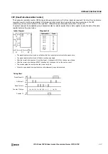
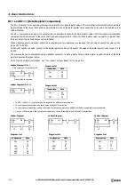
Ladder Diagram
I0
I1
CUDD
C4
100000
I2
Preset Input
Pulse Input
U/D Selection
I3
C4
Q2
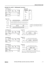
Valid Pulse Inputs
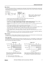
The reset or preset input has priority over the pulse input. One
scan after the reset or preset input has changed from on to off,
the counter starts counting the pulse inputs as they change from
off to on.
100000
100000
Preset Input I0
ON
OFF
Pulse Input I1
ON
OFF
U/D Selection Input I2
ON
OFF
Timing Chart
Counter C4
ON
OFF
100000
100001
Counter C4 Value
100000
0
1
• • •
• • •
99999
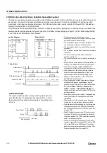
LOD
LOD
LOD
CUDD
LOD
AND
OUT
Instruction
Data
I0
I1
I2
C4
100000
I3
C4
Q2
Reset/Preset
ON
OFF
Pulse
ON
OFF
More than one scan
time is required.
Valid
Invalid
Valid
Program List
Содержание MICROSmart FC6A Series
Страница 1: ...B 1726 7 FC6A SERIES Ladder Programming Manual ...
Страница 8: ...Preface 7 FC6A SERIES MICROSMART LADDER PROGRAMMING MANUAL FC9Y B1726 ...
Страница 32: ...1 OPERATION BASICS 1 20 FC6A SERIES MICROSMART LADDER PROGRAMMING MANUAL FC9Y B1726 ...
Страница 96: ...3 INSTRUCTIONS REFERENCE 3 18 FC6A SERIES MICROSMART LADDER PROGRAMMING MANUAL FC9Y B1726 ...
Страница 130: ...4 BASIC INSTRUCTIONS 4 34 FC6A SERIES MICROSMART LADDER PROGRAMMING MANUAL FC9Y B1726 ...
Страница 158: ...6 DATA COMPARISON INSTRUCTIONS 6 10 FC6A SERIES MICROSMART LADDER PROGRAMMING MANUAL FC9Y B1726 ...
Страница 192: ...9 SHIFT ROTATE INSTRUCTIONS 9 12 FC6A SERIES MICROSMART LADDER PROGRAMMING MANUAL FC9Y B1726 ...
Страница 216: ...10 DATA CONVERSION INSTRUCTIONS 10 24 FC6A SERIES MICROSMART LADDER PROGRAMMING MANUAL FC9Y B1726 ...
Страница 248: ...11 WEEK PROGRAMMER INSTRUCTIONS 11 32 FC6A SERIES MICROSMART LADDER PROGRAMMING MANUAL FC9Y B1726 ...
Страница 272: ...12 DISPLAY INSTRUCTIONS 12 24 FC6A SERIES MICROSMART LADDER PROGRAMMING MANUAL FC9Y B1726 ...
Страница 284: ...14 REFRESH INSTRUCTIONS 14 6 FC6A SERIES MICROSMART LADDER PROGRAMMING MANUAL FC9Y B1726 ...
Страница 288: ...15 INTERRUPT CONTROL INSTRUCTIONS 15 4 FC6A SERIES MICROSMART LADDER PROGRAMMING MANUAL FC9Y B1726 ...
Страница 294: ...16 COORDINATE CONVERSION INSTRUCTIONS 16 6 FC6A SERIES MICROSMART LADDER PROGRAMMING MANUAL FC9Y B1726 ...
Страница 374: ...18 PULSE OUTPUT INSTRUCTIONS 18 78 FC6A SERIES MICROSMART LADDER PROGRAMMING MANUAL FC9Y B1726 Setting ...
Страница 450: ...20 DUAL TEACHING TIMER INSTRUCTIONS 20 4 FC6A SERIES MICROSMART LADDER PROGRAMMING MANUAL FC9Y B1726 ...
Страница 502: ...25 DATA LOG INSTRUCTIONS 25 22 FC6A SERIES MICROSMART LADDER PROGRAMMING MANUAL FC9Y B1726 ...
Страница 546: ...26 SCRIPT 26 44 FC6A SERIES MICROSMART LADDER PROGRAMMING MANUAL FC9Y B1726 ...
Страница 574: ...27 FLOW CALCULATION INSTRUCTIONS 27 28 FC6A SERIES MICROSMART LADDER PROGRAMMING MANUAL FC9Y B1726 ...
Страница 583: ...FC6A SERIES MICROSMART LADDER PROGRAMMING MANUAL FC9Y B1726 28 9 28 USER DEFINED MACRO INSTRUCTION ...
Страница 584: ...28 USER DEFINED MACRO INSTRUCTION 28 10 FC6A SERIES MICROSMART LADDER PROGRAMMING MANUAL FC9Y B1726 ...
Страница 598: ...APPENDIX A 14 FC6A SERIES MICROSMART LADDER PROGRAMMING MANUAL FC9Y B1726 ...


