


FC6A S
ERIES
MICROS
MART
L
ADDER
P
ROGRAMMING
M
ANUAL
FC9Y-B1726
19-11
19: PID C
ONTROL
I
NSTRUCTION
11. Alarm Value
Set the value that will be the trigger condition for Alarm Type (10). The value to set differs by the alarm type.
The content for the alarm value is as follows.
*1 No alarm action when the alarm value is 0.
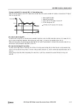
12. Hysteresis
Set the range from the alarm action point to when the alarm output changes from ON to OFF.
When hysteresis is set to a large value, the alarm output will not change by slight variations. When hysteresis is set to a small
value, the alarm output will change by slight variations near the alarm action point, which may negatively impact connected
equipment.
The range is 0.1 to 6,553.5 (°C/°F) or 1 to 65,535 (voltage/current input).
However, when the alarm type is
Upper/Lower Limit Alarm
or
Upper/Lower Limit Alarm with Standby
, you must set
hysteresis so that 1
≤
hysteresis < Alarm Value (11) is satisfied.
13. Delay Time
Set the time until the alarm output is turned ON after the condition to turn the alarm output ON is satisfied.
The delay time prevents the alarm output from turning ON unintentionally when there are fluctuations in the process variable
due to the effects of noise.
After the condition to turn the alarm output ON has been satisfied, if it is no longer satisfied by when the delay time elapses, the
alarm output does not turn ON.
The range is 0 to 10,000 s. When 0, the delay time is disabled.
Alarm Type
Alarm Value
Range
Upper Limit Alarm
Set the deviation from the set point.
When the process variable is current/voltage
or a data register:
-32,768 to 32,767
When the process variable is a thermocouple
or resistance thermometer and the data type
is set to Celsius or Fahrenheit:
-3,276.8 to 3,276.7ºC/ºF
Lower Limit Alarm
Upper/Lower Limit Alarm
When the process variable is current/voltage
or a data register:
0 to 65,535
When the process variable is a thermocouple
or resistance thermometer and the data type
is set to Celsius or Fahrenheit:
0.0 to 6,553.5ºC/ºF
Upper/Lower Limit Range Alarm
Process High Alarm
Set the value where the alarm will operate as
an absolute value.
Minimum to maximum
Process Low Alarm
Upper Limit Alarm with Standby
Set the deviation from the set point.
When the process variable is current/voltage
or a data register:
-32,768 to 32,767
When the process variable is a thermocouple
or resistance thermometer and the data type
is set to Celsius or Fahrenheit:
-3,276.8 to 3,276.7ºC/ºF
Lower Limit Alarm with Standby
Upper/Lower Limit Alarm with Standby
Set the deviation from the set point.
When the process variable is current/voltage
or a data register:
0 to 65,535
When the process variable is a thermocouple
or resistance thermometer and the data type
is set to Celsius or Fahrenheit:
0.0 to 6,553.5ºC/ºF
Содержание MICROSmart FC6A Series
Страница 1: ...B 1726 7 FC6A SERIES Ladder Programming Manual ...
Страница 8: ...Preface 7 FC6A SERIES MICROSMART LADDER PROGRAMMING MANUAL FC9Y B1726 ...
Страница 32: ...1 OPERATION BASICS 1 20 FC6A SERIES MICROSMART LADDER PROGRAMMING MANUAL FC9Y B1726 ...
Страница 96: ...3 INSTRUCTIONS REFERENCE 3 18 FC6A SERIES MICROSMART LADDER PROGRAMMING MANUAL FC9Y B1726 ...
Страница 130: ...4 BASIC INSTRUCTIONS 4 34 FC6A SERIES MICROSMART LADDER PROGRAMMING MANUAL FC9Y B1726 ...
Страница 158: ...6 DATA COMPARISON INSTRUCTIONS 6 10 FC6A SERIES MICROSMART LADDER PROGRAMMING MANUAL FC9Y B1726 ...
Страница 192: ...9 SHIFT ROTATE INSTRUCTIONS 9 12 FC6A SERIES MICROSMART LADDER PROGRAMMING MANUAL FC9Y B1726 ...
Страница 216: ...10 DATA CONVERSION INSTRUCTIONS 10 24 FC6A SERIES MICROSMART LADDER PROGRAMMING MANUAL FC9Y B1726 ...
Страница 248: ...11 WEEK PROGRAMMER INSTRUCTIONS 11 32 FC6A SERIES MICROSMART LADDER PROGRAMMING MANUAL FC9Y B1726 ...
Страница 272: ...12 DISPLAY INSTRUCTIONS 12 24 FC6A SERIES MICROSMART LADDER PROGRAMMING MANUAL FC9Y B1726 ...
Страница 284: ...14 REFRESH INSTRUCTIONS 14 6 FC6A SERIES MICROSMART LADDER PROGRAMMING MANUAL FC9Y B1726 ...
Страница 288: ...15 INTERRUPT CONTROL INSTRUCTIONS 15 4 FC6A SERIES MICROSMART LADDER PROGRAMMING MANUAL FC9Y B1726 ...
Страница 294: ...16 COORDINATE CONVERSION INSTRUCTIONS 16 6 FC6A SERIES MICROSMART LADDER PROGRAMMING MANUAL FC9Y B1726 ...
Страница 374: ...18 PULSE OUTPUT INSTRUCTIONS 18 78 FC6A SERIES MICROSMART LADDER PROGRAMMING MANUAL FC9Y B1726 Setting ...
Страница 450: ...20 DUAL TEACHING TIMER INSTRUCTIONS 20 4 FC6A SERIES MICROSMART LADDER PROGRAMMING MANUAL FC9Y B1726 ...
Страница 502: ...25 DATA LOG INSTRUCTIONS 25 22 FC6A SERIES MICROSMART LADDER PROGRAMMING MANUAL FC9Y B1726 ...
Страница 546: ...26 SCRIPT 26 44 FC6A SERIES MICROSMART LADDER PROGRAMMING MANUAL FC9Y B1726 ...
Страница 574: ...27 FLOW CALCULATION INSTRUCTIONS 27 28 FC6A SERIES MICROSMART LADDER PROGRAMMING MANUAL FC9Y B1726 ...
Страница 583: ...FC6A SERIES MICROSMART LADDER PROGRAMMING MANUAL FC9Y B1726 28 9 28 USER DEFINED MACRO INSTRUCTION ...
Страница 584: ...28 USER DEFINED MACRO INSTRUCTION 28 10 FC6A SERIES MICROSMART LADDER PROGRAMMING MANUAL FC9Y B1726 ...
Страница 598: ...APPENDIX A 14 FC6A SERIES MICROSMART LADDER PROGRAMMING MANUAL FC9Y B1726 ...


