


19: PID C
ONTROL
I
NSTRUCTION
19-36
FC6A S
ERIES
MICROS
MART
L
ADDER
P
ROGRAMMING
M
ANUAL
FC9Y-B1726
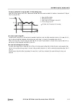
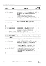
S1+30, S1+31 MV Low Limit
Set MV Low Limit between 0.0 and 100.0 (0.0 and 100.0%).
If the value of MV Low Limit is less than 0.0 or greater than 100.0, the
instruction operates with 0.0. If MV High Limit
≤
MV Low Limit, the
instruction operates with MV Low Limit as 0.0 and MV High Limit as
100.0. Error code 103 will be stored in Error Status (S1+34, S1+35) in
those cases.
R/W
Yes
S1+32, S1+33 MV High Limit
Set MV High Limit between 0.0 and 100.0 (0.0 and 100.0%).
If the value of MV High Limit is less than 0.0 or greater than 100.0, the
instruction operates with 100.0. If MV High Limit
≤
MV Low Limit, the
instruction operates with MV Low Limit as 0.0 and MV High Limit as
100.0. Error code 103 will be stored in Error Status (S1+34, S1+35) in
those cases.
R/W
Yes
S1+34, S1+35 Error Status
The PIDD instruction error status is stored as data type D (double-
word).
For details on error codes, see "Error Status (S1+34, S1+35)" on page
19-37.
R
—
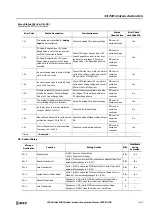
S1+36 to
S1+43
—
Reserved
—
—
—
—
S1+44, S1+45 SP Lower Range Value
Stores the same value as PV Lower Range Value (S1+22, S1+23).
R
—
S1+46, S1+47 SP Upper Range Value
Stores the same value as PV Upper Range Value (S1+24, S1+25).
R
—
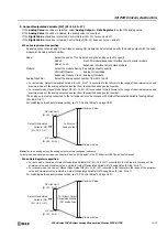
S1+48, S1+49
Output Manipulated Variable
while PID Control is Inhibited
Set the output manipulated variable while PID Inhibit (S3+11) is on
and PID control is inhibited. Set the value as data type F (float)
between 0.0 and 100.0 (0.0 and 100.0%).
While PID Inhibit (S3+11) is off, the value of Output Manipulated
Variable (S1+16, S1+17) for the PIDD instruction is copied to "Output
Manipulated Variable while PID Control is Inhibited (S1+48, S1+49)".
R/W
Yes
S1+50, S1+51 Input Deviation (Offset)
Stores the proportion (%) of the difference (offset) between the set point
(SP) and process variable (PV) for the full scale of the process variable.
R
—
S1+52 to
S1+63
—
Reserved
—
—
—
—
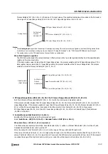
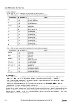
S1+64, S1+65 Control period
Set the cycle to perform on/off control of Control Output (S3+14) from
Output Manipulated Variable.
Set Control Period as data type F (float) between 0.1 and 50.0
seconds. The control period operates as 0.1 seconds if set to a value
less than 0.1 seconds, and it operates as 50.0 seconds if set to a value
greater than or equal to 50.1 seconds. Error code 132 will be stored in
Error Status (S1+34, S1+35) in those cases.
R/W
—
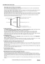
S1+66, S1+67
Output Manipulated Variable
(MV) Analog Value
• When
Analog Output
is specified for Output Manipulated Variable:
Stores the value of Output Manipulated Variable (S1+16, S1+17)
converted to the full scale in the range of the minimum value and
maximum value of the analog output.
• When
Data Register
is specified for Output Manipulated Variable:
Stores the value of Output Manipulated Variable (S1+16, S1+17)
converted to the full scale in the range of the minimum value and
maximum value.
R
—
S1+68 to
S1+99
—
Reserved
—
—
—
—
Allocation
Function
Setting Details
R/W
Modifiable
during
Execution
Содержание MICROSmart FC6A Series
Страница 1: ...B 1726 7 FC6A SERIES Ladder Programming Manual ...
Страница 8: ...Preface 7 FC6A SERIES MICROSMART LADDER PROGRAMMING MANUAL FC9Y B1726 ...
Страница 32: ...1 OPERATION BASICS 1 20 FC6A SERIES MICROSMART LADDER PROGRAMMING MANUAL FC9Y B1726 ...
Страница 96: ...3 INSTRUCTIONS REFERENCE 3 18 FC6A SERIES MICROSMART LADDER PROGRAMMING MANUAL FC9Y B1726 ...
Страница 130: ...4 BASIC INSTRUCTIONS 4 34 FC6A SERIES MICROSMART LADDER PROGRAMMING MANUAL FC9Y B1726 ...
Страница 158: ...6 DATA COMPARISON INSTRUCTIONS 6 10 FC6A SERIES MICROSMART LADDER PROGRAMMING MANUAL FC9Y B1726 ...
Страница 192: ...9 SHIFT ROTATE INSTRUCTIONS 9 12 FC6A SERIES MICROSMART LADDER PROGRAMMING MANUAL FC9Y B1726 ...
Страница 216: ...10 DATA CONVERSION INSTRUCTIONS 10 24 FC6A SERIES MICROSMART LADDER PROGRAMMING MANUAL FC9Y B1726 ...
Страница 248: ...11 WEEK PROGRAMMER INSTRUCTIONS 11 32 FC6A SERIES MICROSMART LADDER PROGRAMMING MANUAL FC9Y B1726 ...
Страница 272: ...12 DISPLAY INSTRUCTIONS 12 24 FC6A SERIES MICROSMART LADDER PROGRAMMING MANUAL FC9Y B1726 ...
Страница 284: ...14 REFRESH INSTRUCTIONS 14 6 FC6A SERIES MICROSMART LADDER PROGRAMMING MANUAL FC9Y B1726 ...
Страница 288: ...15 INTERRUPT CONTROL INSTRUCTIONS 15 4 FC6A SERIES MICROSMART LADDER PROGRAMMING MANUAL FC9Y B1726 ...
Страница 294: ...16 COORDINATE CONVERSION INSTRUCTIONS 16 6 FC6A SERIES MICROSMART LADDER PROGRAMMING MANUAL FC9Y B1726 ...
Страница 374: ...18 PULSE OUTPUT INSTRUCTIONS 18 78 FC6A SERIES MICROSMART LADDER PROGRAMMING MANUAL FC9Y B1726 Setting ...
Страница 450: ...20 DUAL TEACHING TIMER INSTRUCTIONS 20 4 FC6A SERIES MICROSMART LADDER PROGRAMMING MANUAL FC9Y B1726 ...
Страница 502: ...25 DATA LOG INSTRUCTIONS 25 22 FC6A SERIES MICROSMART LADDER PROGRAMMING MANUAL FC9Y B1726 ...
Страница 546: ...26 SCRIPT 26 44 FC6A SERIES MICROSMART LADDER PROGRAMMING MANUAL FC9Y B1726 ...
Страница 574: ...27 FLOW CALCULATION INSTRUCTIONS 27 28 FC6A SERIES MICROSMART LADDER PROGRAMMING MANUAL FC9Y B1726 ...
Страница 583: ...FC6A SERIES MICROSMART LADDER PROGRAMMING MANUAL FC9Y B1726 28 9 28 USER DEFINED MACRO INSTRUCTION ...
Страница 584: ...28 USER DEFINED MACRO INSTRUCTION 28 10 FC6A SERIES MICROSMART LADDER PROGRAMMING MANUAL FC9Y B1726 ...
Страница 598: ...APPENDIX A 14 FC6A SERIES MICROSMART LADDER PROGRAMMING MANUAL FC9Y B1726 ...


