


FC6A S
ERIES
MICROS
MART
L
ADDER
P
ROGRAMMING
M
ANUAL
FC9Y-B1726
27-1
27: F
LOW
C
ALCULATION
I
NSTRUCTIONS
This chapter describes the flow calculation instructions that output flow volume and the accumulated flow volume.
SCALE (Convert Analog Input)
This instruction scales the analog input value according to the coordinates between two specified points and outputs that result.
Symbol
Operation
When the input is on, the value of the data register specified by S1 is scaled according to the settings in the data register specified
by S2, then the calculated result is stored in the output value (D1+0, D1+1).
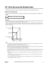
As shown in the diagram below, scaling is calculated by substituting the input value into a linear function that has been derived
from four points that are set by the output maximum value, output minimum value, input maximum value, input minimum value,
which are configured by S2.
Notes:
• The SCALE instruction cannot be used in an interrupt program. If used in an interrupt program, a user program execution error occurs, the
execution of the instruction is canceled, and the next instruction is executed.
For user program execution errors, see "User Program Execution Errors" on page 3-10.
• If the value of S1 or S2 is out of range, the result is a user program execution error. Error code 28 is stored in D8006, and the output value
(D1+0, D1+1) and the output value (dead band) (D1+2, D1+3) are not updated.
For user program execution errors, see "User Program Execution Errors" on page 3-10.
• In the following cases, a user program execution error will occur. Error code 46 is stored in D8006, and the output value (D1+0, D1+1) and
the output value (dead band) (D1+2, D1+3) are not updated. For user program execution errors, see "User Program Execution Errors" on
page 3-10.
• When the input minimum value (S2+1) is the input maximum value (S2+0) or higher (input minimum value (S2+1)
≥
input maximum
value (S2+0))
• When the output minimum value (S2+4, S2+5) is the output maximum value (S2+2, S2+3) or higher (output minimum value (S2+4,
S2+5)
≥
output maximum value (S2+2, S2+3))
• When the output maximum value, the output minimum value, or the dead band (S2+6, S2+7) is INF (infinity) or NAN (not a number)
• When the dead band (S2+6, S2+7) is negative
D2
*****
S2
*****
SCALE(*) S1
*****
D1
*****
S3
*****
0
Output maximum value
Output minimum value
Output value
Input
maximum value
(S1)
(S2+0)
(S2+1)
(S2+4, S2+5)
(S2+2, S2+3)
(D1+0, D1+1)
Input
minimum value
Input value
Содержание MICROSmart FC6A Series
Страница 1: ...B 1726 7 FC6A SERIES Ladder Programming Manual ...
Страница 8: ...Preface 7 FC6A SERIES MICROSMART LADDER PROGRAMMING MANUAL FC9Y B1726 ...
Страница 32: ...1 OPERATION BASICS 1 20 FC6A SERIES MICROSMART LADDER PROGRAMMING MANUAL FC9Y B1726 ...
Страница 96: ...3 INSTRUCTIONS REFERENCE 3 18 FC6A SERIES MICROSMART LADDER PROGRAMMING MANUAL FC9Y B1726 ...
Страница 130: ...4 BASIC INSTRUCTIONS 4 34 FC6A SERIES MICROSMART LADDER PROGRAMMING MANUAL FC9Y B1726 ...
Страница 158: ...6 DATA COMPARISON INSTRUCTIONS 6 10 FC6A SERIES MICROSMART LADDER PROGRAMMING MANUAL FC9Y B1726 ...
Страница 192: ...9 SHIFT ROTATE INSTRUCTIONS 9 12 FC6A SERIES MICROSMART LADDER PROGRAMMING MANUAL FC9Y B1726 ...
Страница 216: ...10 DATA CONVERSION INSTRUCTIONS 10 24 FC6A SERIES MICROSMART LADDER PROGRAMMING MANUAL FC9Y B1726 ...
Страница 248: ...11 WEEK PROGRAMMER INSTRUCTIONS 11 32 FC6A SERIES MICROSMART LADDER PROGRAMMING MANUAL FC9Y B1726 ...
Страница 272: ...12 DISPLAY INSTRUCTIONS 12 24 FC6A SERIES MICROSMART LADDER PROGRAMMING MANUAL FC9Y B1726 ...
Страница 284: ...14 REFRESH INSTRUCTIONS 14 6 FC6A SERIES MICROSMART LADDER PROGRAMMING MANUAL FC9Y B1726 ...
Страница 288: ...15 INTERRUPT CONTROL INSTRUCTIONS 15 4 FC6A SERIES MICROSMART LADDER PROGRAMMING MANUAL FC9Y B1726 ...
Страница 294: ...16 COORDINATE CONVERSION INSTRUCTIONS 16 6 FC6A SERIES MICROSMART LADDER PROGRAMMING MANUAL FC9Y B1726 ...
Страница 374: ...18 PULSE OUTPUT INSTRUCTIONS 18 78 FC6A SERIES MICROSMART LADDER PROGRAMMING MANUAL FC9Y B1726 Setting ...
Страница 450: ...20 DUAL TEACHING TIMER INSTRUCTIONS 20 4 FC6A SERIES MICROSMART LADDER PROGRAMMING MANUAL FC9Y B1726 ...
Страница 502: ...25 DATA LOG INSTRUCTIONS 25 22 FC6A SERIES MICROSMART LADDER PROGRAMMING MANUAL FC9Y B1726 ...
Страница 546: ...26 SCRIPT 26 44 FC6A SERIES MICROSMART LADDER PROGRAMMING MANUAL FC9Y B1726 ...
Страница 574: ...27 FLOW CALCULATION INSTRUCTIONS 27 28 FC6A SERIES MICROSMART LADDER PROGRAMMING MANUAL FC9Y B1726 ...
Страница 583: ...FC6A SERIES MICROSMART LADDER PROGRAMMING MANUAL FC9Y B1726 28 9 28 USER DEFINED MACRO INSTRUCTION ...
Страница 584: ...28 USER DEFINED MACRO INSTRUCTION 28 10 FC6A SERIES MICROSMART LADDER PROGRAMMING MANUAL FC9Y B1726 ...
Страница 598: ...APPENDIX A 14 FC6A SERIES MICROSMART LADDER PROGRAMMING MANUAL FC9Y B1726 ...


