


FC6A S
ERIES
MICROS
MART
L
ADDER
P
ROGRAMMING
M
ANUAL
FC9Y-B1726
18-39
18: P
ULSE
O
UTPUT
I
NSTRUCTIONS
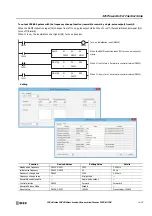
3. S1 (source 1): Control register
S1 specifies the first data register of the data registers to use with ZRN1, ZRN2, ZRN3 or ZRN4 instructions.
Starting from the specified data register, 14 consecutive data registers are used.
Specify the first data register so that the device range is not exceeded.
*1 The upper and lower data registers change according to the 32-bit data storage method specified. For details, see "32-bit Data Storage" on
*2 When ZRN mode 0 is specified for the zero return method, starting 6 to +10 are invalid.
*3 Valid only when
Reversible control (single-pulse output)
or
Reversible control (dual-pulse output)
is selected for reversible control enable.
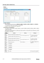
4. S2 (source 2): Initialization Input
S2 specifies the initialization input. When the initialization input S2 is turned on, the initial values configured in the WindLDR
ZRN (Zero
Return)
dialog box, on the
Settings
tab, are stored in the control registers. An external input or an internal relay can be specified.
When the initialization input is on, the initial values are written to the data registers with each scan. (Even when the ZRN
instruction is not executed (when not on), if the initialization input is turned on, the initial values are stored in the data
registers.) To only initialize the values one time, use the initialization input in combination with the SOTU (single output up)
instruction or the SOTD (single output down) instruction.
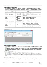
5. S3 (source 3): Proximity Signal
S3 specifies the proximity signal. The pulse frequency starts being decreased with the rise in the proximity signal.
An external input or an internal relay can be specified for the proximity signal.
Notes:
•
Do not use the same input or internal relay as the proximity signal for the ZRN1, ZRN2, ZRN3 and ZRN4 instructions. If they operate
simultaneously, pulse output may not stop even if the proximity signal changes from on to off.
•
To use the high-speed proximity signal, set the relevant input to
Normal Input
under
Special Input
on
Function Area Settings
. Do not
use the input as interrupt input, catch input, high-speed counter, or frequency measurement.
•
When using the high-speed proximity signal, ensure that no bounce occurs in the proximity signal.
Storage
Destination
Function
Setting
Reference
All-in-One CPU
Module
CAN J1939 All-in-
One CPU Module/
Plus CPU Module
Starting 0
Initial pulse frequency
(high word)
ZRN1, ZRN2: 15 to 100,000
(increments of 1 Hz)
ZRN3, ZRN4: 15 to 5,000
(increments of 1 Hz)
ZRN1 to ZRN4:
15 to 100,000
(increments of 1 Hz)
"10. Initial Pulse
Frequency" on page 18-41
Starting 1
Initial pulse frequency
(low word)
Starting 2
Creep pulse frequency
(high word)
ZRN1, ZRN2: 15 to 100,000
(increments of 1 Hz)
ZRN3, ZRN4: 15 to 5,000
(increments of 1 Hz)
ZRN1 to ZRN4:
15 to 100,000
(increments of 1 Hz)
"11. Creep Pulse
Frequency" on page 18-41
Starting 3
Creep pulse frequency
(low word)
Starting 4
Error status
10 to 10,000 ms
"12. Error status" on page
18-41
Starting 5
Reserved
Starting 6
Steady pulse frequency
(high word)
ZRN1, ZRN2: 15 to 100,000
(increments of 1 Hz)
ZRN3, ZRN4: 15 to 5,000
(increments of 1 Hz)
ZRN1 to ZRN4:
15 to 100,000
(increments of 1 Hz)
"13. Steady pulse
frequency" on page 18-41
Starting 7
Steady pulse frequency
(low word)
Starting 8
Acceleration time
10 to 10,000 ms
"14. Acceleration time" on
page 18-41
Starting 9
Deceleration time
10 to 10,000 ms
"15. Deceleration time" on
page 18-42
Starting 10
Control direction
0: Forward
1: Reverse
"18. Control direction" on
page 18-42
Starting 11
Reserved
Starting 12
Reserved
Starting 13
Reserved
Detection Speed
Input Device
Description
High-speed
I0, I1, I3, I4, I6, I7
An interrupt is used to read the proximity signal. The proximity signal can be read without
being affected by the user program scan.
Normal
Inputs except I0, I1,
I3, I4, I6, and I7 and
Internal relays
The information updated in the END processing is read as the proximity signal. It is affected
by the user program scan.
Содержание MICROSmart FC6A Series
Страница 1: ...B 1726 7 FC6A SERIES Ladder Programming Manual ...
Страница 8: ...Preface 7 FC6A SERIES MICROSMART LADDER PROGRAMMING MANUAL FC9Y B1726 ...
Страница 32: ...1 OPERATION BASICS 1 20 FC6A SERIES MICROSMART LADDER PROGRAMMING MANUAL FC9Y B1726 ...
Страница 96: ...3 INSTRUCTIONS REFERENCE 3 18 FC6A SERIES MICROSMART LADDER PROGRAMMING MANUAL FC9Y B1726 ...
Страница 130: ...4 BASIC INSTRUCTIONS 4 34 FC6A SERIES MICROSMART LADDER PROGRAMMING MANUAL FC9Y B1726 ...
Страница 158: ...6 DATA COMPARISON INSTRUCTIONS 6 10 FC6A SERIES MICROSMART LADDER PROGRAMMING MANUAL FC9Y B1726 ...
Страница 192: ...9 SHIFT ROTATE INSTRUCTIONS 9 12 FC6A SERIES MICROSMART LADDER PROGRAMMING MANUAL FC9Y B1726 ...
Страница 216: ...10 DATA CONVERSION INSTRUCTIONS 10 24 FC6A SERIES MICROSMART LADDER PROGRAMMING MANUAL FC9Y B1726 ...
Страница 248: ...11 WEEK PROGRAMMER INSTRUCTIONS 11 32 FC6A SERIES MICROSMART LADDER PROGRAMMING MANUAL FC9Y B1726 ...
Страница 272: ...12 DISPLAY INSTRUCTIONS 12 24 FC6A SERIES MICROSMART LADDER PROGRAMMING MANUAL FC9Y B1726 ...
Страница 284: ...14 REFRESH INSTRUCTIONS 14 6 FC6A SERIES MICROSMART LADDER PROGRAMMING MANUAL FC9Y B1726 ...
Страница 288: ...15 INTERRUPT CONTROL INSTRUCTIONS 15 4 FC6A SERIES MICROSMART LADDER PROGRAMMING MANUAL FC9Y B1726 ...
Страница 294: ...16 COORDINATE CONVERSION INSTRUCTIONS 16 6 FC6A SERIES MICROSMART LADDER PROGRAMMING MANUAL FC9Y B1726 ...
Страница 374: ...18 PULSE OUTPUT INSTRUCTIONS 18 78 FC6A SERIES MICROSMART LADDER PROGRAMMING MANUAL FC9Y B1726 Setting ...
Страница 450: ...20 DUAL TEACHING TIMER INSTRUCTIONS 20 4 FC6A SERIES MICROSMART LADDER PROGRAMMING MANUAL FC9Y B1726 ...
Страница 502: ...25 DATA LOG INSTRUCTIONS 25 22 FC6A SERIES MICROSMART LADDER PROGRAMMING MANUAL FC9Y B1726 ...
Страница 546: ...26 SCRIPT 26 44 FC6A SERIES MICROSMART LADDER PROGRAMMING MANUAL FC9Y B1726 ...
Страница 574: ...27 FLOW CALCULATION INSTRUCTIONS 27 28 FC6A SERIES MICROSMART LADDER PROGRAMMING MANUAL FC9Y B1726 ...
Страница 583: ...FC6A SERIES MICROSMART LADDER PROGRAMMING MANUAL FC9Y B1726 28 9 28 USER DEFINED MACRO INSTRUCTION ...
Страница 584: ...28 USER DEFINED MACRO INSTRUCTION 28 10 FC6A SERIES MICROSMART LADDER PROGRAMMING MANUAL FC9Y B1726 ...
Страница 598: ...APPENDIX A 14 FC6A SERIES MICROSMART LADDER PROGRAMMING MANUAL FC9Y B1726 ...


