


FC6A S
ERIES
MICROS
MART
L
ADDER
P
ROGRAMMING
M
ANUAL
FC9Y-B1726
4-9
4: B
ASIC
I
NSTRUCTIONS
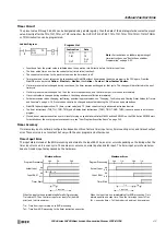
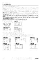
Timer Circuit
The preset value 0 through 65,535 can be designated using a data register; then the data of the data register becomes the preset
value. Directly after the TML, TIM, TMH, or TMS instruction, the OUT, OUTN, SET, RST, TML, TIM, TMH, TMS, TMLO, TIMO, TMHO,
or TMSO instruction can be programmed.
• Countdown from the preset value is initiated when the operation result directly before the timer input is on.
• The timer output turns on when the current value (timed value) reaches 0.
• The current value returns to the preset value when the timer input is off.
• Timer preset and current values can be changed using WindLDR without downloading the entire program to the CPU again. From the
WindLDR menu bar, select
Online
>
Monitor > Monitor
, then
Online
>
Custom
>
New Custom Monitor
.
• If a timer preset value is changed during countdown, the timer remains unchanged for that cycle. The change will be reflected in the next
time cycle.
• If a timer preset value is changed to 0, then the timer stops operation, and the timer output is turned on immediately.
• If a current value is changed during countdown, the change becomes effective immediately.
• For data movement when changing, confirming, and clearing preset values, see "Changing, Confirming, and Clearing Preset Values for Timers
and Counters" on page 4-19. Preset values can also be changed and confirmed using the LCD screen and pushbuttons.
• WindLDR ladder diagrams show TP (timer preset value) and TC (timer current value) in advanced instruction devices.
• The timer instructions (TML, TIM, TMH, TMS) and off-delay timer instructions (TMLO, TIMO, TMHO, TMSO) cannot be used in an interrupt
program.
• If used, a user program execution error will result, turning on special internal relay M8004 and the ERR LED on the FC6A Series MICROSmart.
For details about the user program execution errors, see "User Program Execution Errors" on page 3-10.
Timer Accuracy
Timer accuracy due to software configuration depends on three factors: timer input error, timer counting error, and timeout output
error. These errors are not constant but vary with the user program and other causes.
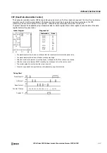
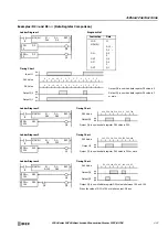
Timer Input Error
The input status is read at the END processing and stored to the input RAM. So, an error occurs depending on the timing when the
timer input turns on in a scan cycle. The same error occurs on normal input and catch input. The timer input error shown below
does not include input delay caused by the hardware.
I1
Ladder Diagram
TIM
D10
T5
Q0
LOD
TIM
OUT
I1
T5
D10
Q0
Instruction
Data
Note:
For restrictions on ladder programming of
timer instructions, see "Restriction on Ladder
Programming" on page 4-33.
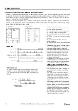
Program List
Program Processing
Actual Input
ON
OFF
Input RAM
ON
OFF
Timer Start
Minimum Error
Tie
END
1 scan time
TIM
END
Tet
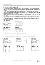
Program Processing
Actual Input
ON
OFF
Input RAM
ON
OFF
Timer Start
Maximum Error
END
1 scan time
TIM
END
Tet
TIM
Tie
When the input turns on immediately before END processing,
Tie is almost 0. Then the timer input error is only Tet (behind
error) and is at its minimum.
When the input turns on immediately after END processing, Tie is
almost equal to one scan time. Then the timer input error is Tie +
Tet = one scan time + Tet (behind error) and is at its maximum.
Tie: Time from input turning on to END processing
Tet: Time from END processing to the timer instruction execution
Содержание MICROSmart FC6A Series
Страница 1: ...B 1726 7 FC6A SERIES Ladder Programming Manual ...
Страница 8: ...Preface 7 FC6A SERIES MICROSMART LADDER PROGRAMMING MANUAL FC9Y B1726 ...
Страница 32: ...1 OPERATION BASICS 1 20 FC6A SERIES MICROSMART LADDER PROGRAMMING MANUAL FC9Y B1726 ...
Страница 96: ...3 INSTRUCTIONS REFERENCE 3 18 FC6A SERIES MICROSMART LADDER PROGRAMMING MANUAL FC9Y B1726 ...
Страница 130: ...4 BASIC INSTRUCTIONS 4 34 FC6A SERIES MICROSMART LADDER PROGRAMMING MANUAL FC9Y B1726 ...
Страница 158: ...6 DATA COMPARISON INSTRUCTIONS 6 10 FC6A SERIES MICROSMART LADDER PROGRAMMING MANUAL FC9Y B1726 ...
Страница 192: ...9 SHIFT ROTATE INSTRUCTIONS 9 12 FC6A SERIES MICROSMART LADDER PROGRAMMING MANUAL FC9Y B1726 ...
Страница 216: ...10 DATA CONVERSION INSTRUCTIONS 10 24 FC6A SERIES MICROSMART LADDER PROGRAMMING MANUAL FC9Y B1726 ...
Страница 248: ...11 WEEK PROGRAMMER INSTRUCTIONS 11 32 FC6A SERIES MICROSMART LADDER PROGRAMMING MANUAL FC9Y B1726 ...
Страница 272: ...12 DISPLAY INSTRUCTIONS 12 24 FC6A SERIES MICROSMART LADDER PROGRAMMING MANUAL FC9Y B1726 ...
Страница 284: ...14 REFRESH INSTRUCTIONS 14 6 FC6A SERIES MICROSMART LADDER PROGRAMMING MANUAL FC9Y B1726 ...
Страница 288: ...15 INTERRUPT CONTROL INSTRUCTIONS 15 4 FC6A SERIES MICROSMART LADDER PROGRAMMING MANUAL FC9Y B1726 ...
Страница 294: ...16 COORDINATE CONVERSION INSTRUCTIONS 16 6 FC6A SERIES MICROSMART LADDER PROGRAMMING MANUAL FC9Y B1726 ...
Страница 374: ...18 PULSE OUTPUT INSTRUCTIONS 18 78 FC6A SERIES MICROSMART LADDER PROGRAMMING MANUAL FC9Y B1726 Setting ...
Страница 450: ...20 DUAL TEACHING TIMER INSTRUCTIONS 20 4 FC6A SERIES MICROSMART LADDER PROGRAMMING MANUAL FC9Y B1726 ...
Страница 502: ...25 DATA LOG INSTRUCTIONS 25 22 FC6A SERIES MICROSMART LADDER PROGRAMMING MANUAL FC9Y B1726 ...
Страница 546: ...26 SCRIPT 26 44 FC6A SERIES MICROSMART LADDER PROGRAMMING MANUAL FC9Y B1726 ...
Страница 574: ...27 FLOW CALCULATION INSTRUCTIONS 27 28 FC6A SERIES MICROSMART LADDER PROGRAMMING MANUAL FC9Y B1726 ...
Страница 583: ...FC6A SERIES MICROSMART LADDER PROGRAMMING MANUAL FC9Y B1726 28 9 28 USER DEFINED MACRO INSTRUCTION ...
Страница 584: ...28 USER DEFINED MACRO INSTRUCTION 28 10 FC6A SERIES MICROSMART LADDER PROGRAMMING MANUAL FC9Y B1726 ...
Страница 598: ...APPENDIX A 14 FC6A SERIES MICROSMART LADDER PROGRAMMING MANUAL FC9Y B1726 ...


