


146
Part 1 Specification
[4] Output control signals (Axis 1 = Direct numerical specification mode)
An example of control signals of axis (1) is explained.
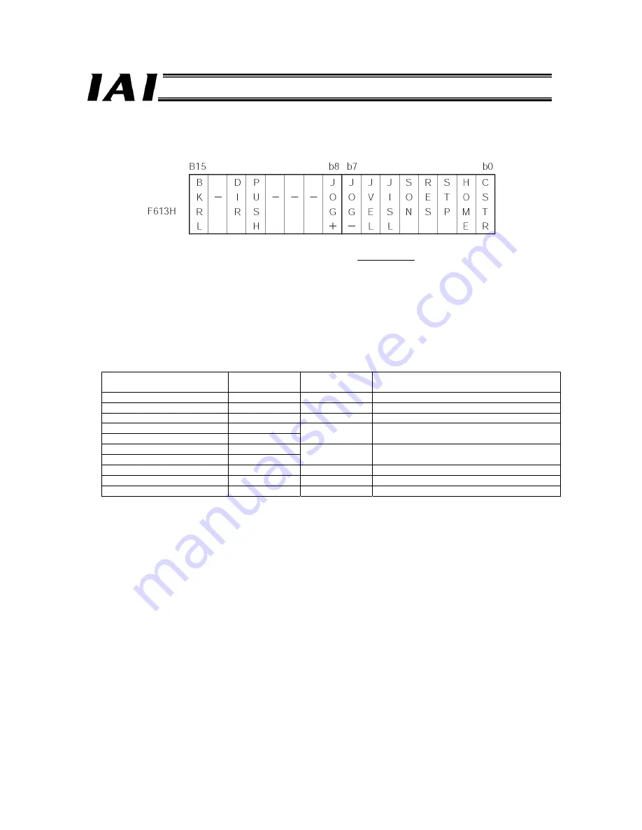
The configuration of the control signal register of axis (1) is shown below.
The method of use is the same as in [3], except for the DIR and PUSH.
The DIR and PUSH signals are used as a set when performing push operation in the direct numerical specification
mode.
•
PUSH signal: The push mode is effective when this signal is “1.”
•
DIR signal:
This signal specifies the push direction.
“0” = Home return direction “1” = Opposite home return direction
In other conditions, the push speed corresponds to the specification of parameter No. 34, while the maximum push
amount corresponds to the specified positioning band.
A query in the push operation mode is described below.
z
Query
Field name
RTU mode data
(8 bits)
Data length
(bytes)
Remarks
Header None
-
Slave address
3F H
1
Fixed.
Function code
06 H
1
Starting address
(upper)
F6 H
Starting address
(lower)
13 H
2
Address of the control signal register of axis (1)
New data (data written) (upper)
30 H
New data (data written) (lower)
10 H
2
Set DIR, PUSH and SON to “1.”
Error check
(CRC)
16 bits
2
Based on calculation result (5A95)
Trailer None
-
Total bytes
8
z
Response
If the data has been changed (written) successfully, the response is the same as the query.
z
Actual Example
Sent Query:
3F06F61330105A95
Received Response: 3F06F61330105A95
Address
Содержание RoboNet
Страница 1: ...Operation Manual Forth Edition ROBONET ...
Страница 242: ...222 Part 1 Specification 5 4 3 External Dimensions 50 from DIN rail center 35 mm DIN rail 69 3 from DIN rail surface ...
Страница 257: ...237 Part 2 Startup Chapter X Installed face down X Installed face up ...
Страница 354: ...334 ...
Страница 395: ...375 ...
Страница 396: ...376 ...
Страница 397: ...377 ...


