


Rev. 1.00
269 of 486
July 31, 2018
32-Bit Arm
®
Cortex
®
-M0+ MCU
HT32F50231/HT32F50241
14 Pulse W
idth Modulator (PWM)
Bits
Field
Descriptions
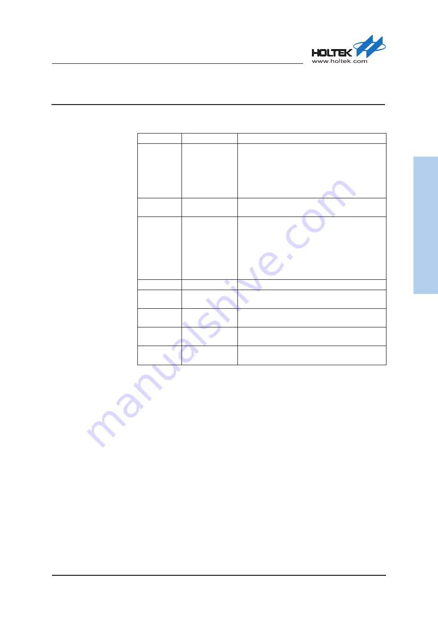
[18:16]
MMSEL
Master Mode Selection
Master mode selection is used to select the MTO signal source which is used to
synchronize the other slave timer.
MMSEL [2:0]
Mode
Descriptions
000
Reset Mode
The MTO signal in the Reset mode is an output
derived from one of the following cases:
1. Software setting UEVG bit
2. The STI trigger input signal which will be
output on the MTO signal line when the Timer
is used in the slave Restart mode
001
Enable Mode
The Counter Enable signal is used as the trigger
output.
010
Update Mode
The update event is used as the trigger output
according to one of the following cases when the
UEVDIS bit is cleared to 0:
1. Counter overflow / underflow
2. Software setting UEVG
3. Slave trigger input when used in slave restart
mode
011
—
Reserved
100
Compare Mode 0
The Channel 0 Output reference signal named
CH0OREF is used as the trigger output.
101
Compare Mode 1
The Channel 1 Output reference signal named
CH1OREF is used as the trigger output.
110
Compare Mode 2
The Channel 2 Output reference signal named
CH2OREF is used as the trigger output.
111
Compare Mode 3
The Channel 3 Output reference signal named
CH3OREF is used as the trigger output.


