SJ100DN Inverter
49
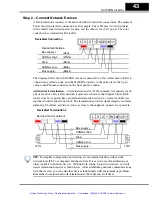
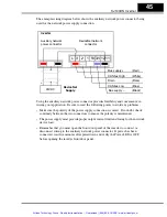
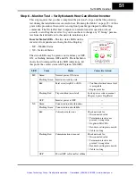
Polled I/O Data Map, Inverter Outputs
– The polled I/O for the inverter maps to four
words (16 bits each) input data, and four words output data. This represents a small
portion of the inverter’s parameters and commands—just those required to manage
motor operation in real time. Some data words contain discrete (individual) bits (used as
flags), while others words contain values (used as scalar numbers). When the network is
active, polled I/O data is automatically updated on each network scan.
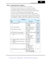
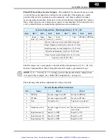
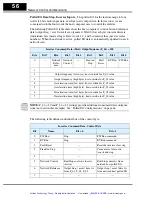
The I/O image above corresponds to the default (Host) Input Instance P_47 = 101. The
Inverter Consumed Data, (Host) Output Instance I/O image is presented in Step 7.
NOTE:
P_47 = 70 and P_47 = 71 settings provide other produced data configurations
(not used in this example). See “Polled I/O Configurations” on page 66.
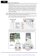
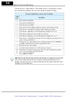
The following table defines individual bits of the status byte.
Inverter Produced Data, (Host) Input Instance (P_47) = 101
Byte
Bit 7
Bit 6
Bit 5
Bit 4
Bit 3
Bit 2
Bit 1
Bit 0
0
Input
term. [3]
Input
term. [2]
Input
term. [1]
Freq.
Arrival
—
Trip
RV Run
FW Run
1
Inverter status (see status code table, next page)
2
Output frequency monitor (low byte), D_01 value
3
Output frequency monitor (high byte), D_01 value
4
Output current monitor (low byte), D_02 value
5
Output current monitor (high byte), D_02 value
6
Trip error code, D_08 value
7
—
Inverter Produced Data, Status Byte
Bit
Name
Bit = 0
Bit = 1
0
FW Run
Inverter stopped or in RV
Inverter in FW Run
1
RV Run
Inverter stopped or in FW
Inverter in RV Run
2
Trip
No faults exist
Trip exists, not cleared
3
—
—
—
4
Frequency arrival
Inverter stopped, or in accel or
decel
Inverter output arrived at
target freq.
5
Input terminal [1]
Input [1] = OFF
Input [1] = ON
6
Input terminal [2]
Input [2] = OFF
Input [2] = ON
7
Input terminal [3]
Input [3] = OFF
Input [3] = ON
Artisan Technology Group - Quality Instrumentation ... Guaranteed | (888) 88-SOURCE | www.artisantg.com

