


SJ100DN Inverter
67
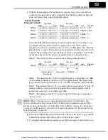
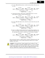
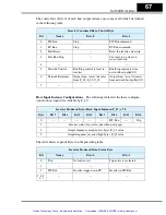
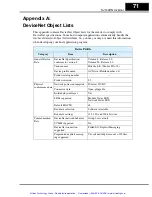
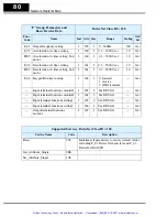
The control bits (Byte 0) of each host output instance use some or all of the bits defined
in the following table.
Host Input Instance Configurations
– The following tables list the three configura-
tions for host input data (settable by P_47).
The table below expands Byte 0 in the preceding table.
Inverter Consumed Data, Control Byte
Bit
Name
Bit = 0
Bit = 1
0
FW Run
Stop
FW Run command
1
RV Run
Stop
RV Run command
2
Fault Reset
—
Reset the inverter, clear trip
3
Free Run Stop
—
Cause motor to free run
(coast) and stop
4
—
—
—
5
Network Control
Run/Stop control is local to
inverter
Run/Stop control is from
network host polled I/O
6
Network Reference
Output freq. / accel / decel is
from F_01, F_02, F_03
Output freq. / accel / decel is
from network host polled I/O
7
—
—
—
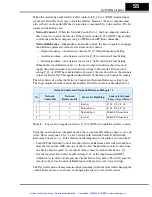
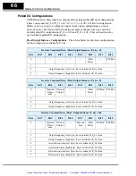
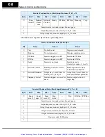
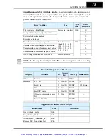
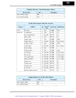
Inverter Produced Data, (Host) Input Instance (P_47) = 70
Byte
Bit 7
Bit 6
Bit 5
Bit 4
Bit 3
Bit 2
Bit 1
Bit 0
0
—
—
—
—
—
FW Run
—
Trip
1
Inverter status (see status code table, next page)
2
Output frequency monitor (low byte), D_01 value
3
Output frequency monitor (high byte), D_01 value
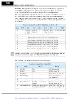
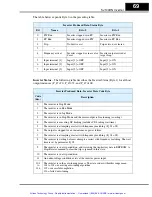
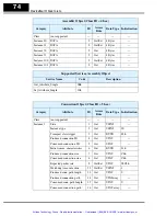
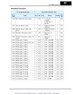
Inverter Produced Data, Status Byte
Bit
Name
Bit = 0
Bit = 1
0
Trip
No faults exist
Trip exists, not cleared
1
—
—
—
2
FW Run
Inverter stopped or in RV
Inverter in FW Run
3, 4, 5,
6, 7
—
—
—
Artisan Technology Group - Quality Instrumentation ... Guaranteed | (888) 88-SOURCE | www.artisantg.com


