SJ100DN Inverter
33
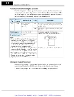
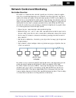
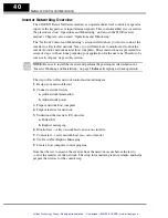
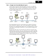
Specifications of Control and Logic Connections
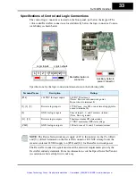
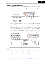
The control logic connector is located on the front panel, just below the keypad. The
color-coded DeviceNet connector is located directly below the logic connector. Connec-
tor labeling is shown below.
Specifications for the logic connection terminals are in the following table:
NOTE:
The DeviceNet network must 24V to the inverter via the [V+] (Red)
and [V–] (Black) terminals on the DeviceNet connector. DO NOT attempt to use the
inverter’s internal 24VDC supply (on [P24] and [L]) for DeviceNet network power.
The DeviceNet connector signals must meet the electrical requirements given by the
DeviceNet industry standards. For more information, visit the Open DeviceNet Vendor
Association website at http://www.odva.org.
Logic inputs
Logic outputs
L 3
1
2
P24 CM2 12 11
DeviceNet network
connector
Auxiliary network
power connector
Terminal Name
Description
Ratings
[P24]
+24VDC for logic inputs
24VDC, 30 mA max
(Notes: Do not use for network power
Do not short to terminal L)
[1], [2], [3]
Discrete logic inputs
27VDC max. (use P24 or an external supply refer-
enced to terminal L)
[L]
GND for logic inputs
Sum of input 1, 2, and 3 currents (return)
(Note: Do not ground)
[11], [12]
Discrete logic outputs
50mA maximum ON state current,
27 VDC maximum OFF state voltage
[CM2]
GND for logic outputs
100 mA: sum of 11 and 12 currents (return)
Artisan Technology Group - Quality Instrumentation ... Guaranteed | (888) 88-SOURCE | www.artisantg.com


