SJ100DN Inverter
53
j.
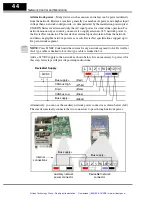
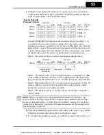
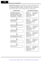
With the inverter output ON and the motor rotating, now you can use the host
computer to monitor the inverter’s polled I/O. The following diagram shows the
expected (typical) data, using the default settings.
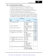
Using the Polled I/O Data Map for produced (output) data given in Step 5, you
can interpret the data sent to the host computer. For scalar values such as
frequency and current, a scale factor of 1, 10, 100, or 1000 applies. The “Network
Register Map” on page 78 lists the inverters parameters and the scale factor used
to get/set the parameter value over the network. To get a parameter’s actual value,
divide the value sent by the inverter (in decimal form) by the scale factor.
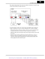
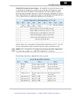
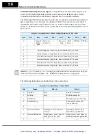
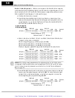
• Word 0 – The status bits that are set have the meanings indicated below:
• Word 1 – The decimal value “1500” for output frequency corresponds to 15.00Hz
(D_01 reading) when the scale factor of 100 is applied. Recall that the powerup
test procedure for the installation set F_01 = 15.0Hz (restore this value if needed).
• Word 2 – The decimal value of “11” for output current corresponds to 1.1A (D_02
reading) when the scale factor of 10 is applied. This value represents a small
inverter and motor size; your reading may differ.
• Word 3 – The decimal value of “0” for trip code (D_08 reading) corresponds to
“no trip” status.
NOTE:
When a trip event occurs, the polled I/O will indicate it by Trip Bit = 1 in
Word 0 and the actual Trip Code in Word 3. When the trip condition is cleared (Stop/
Reset key), then the Trip bit = 0, but the Trip Code in Word 3 remains. To clear it also,
you must clear the inverter’s trip history. For more information, see “Restoring Factory
Default Settings” on page 99.
k.
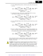
Press the Stop/Reset key on the inverter. This will cause the motor to stop, and the
Polled I/O (produced data) shown above will return to 0 values.
l.
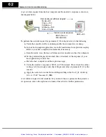
To complete this monitoring sequence, stop the host computer’s DeviceNet scan.
MSB
LSB
High byte
MSB
LSB
Low byte
Word 0
Word 1
Word 2
Word 3
0111h
05DCh
000Bh
0000h
Hex
273
1500
11
0
Decimal
Inverter Polled I/O
Produced (Output)
0 0 0 0
0 0 0 0
0 0 0 0
0 0 0 0
0 0 0 0
0 1 0 1
0 0 0 0
0 0 0 1
0 0 0 0
0 0 0 0
1 1 0 1
1 1 0 0
0 0 0 0
1 0 1 1
0 0 0 1
0 0 0 1
MSB
LSB
High byte
MSB
LSB
Low byte
Word 0
0111h
Hex
273
Decimal
Inverter state = 1
(Run Mode)
Freq. arrival
FW Run
0 0 0 0
0 0 0 1
0 0 0 1
0 0 0 1
Artisan Technology Group - Quality Instrumentation ... Guaranteed | (888) 88-SOURCE | www.artisantg.com

