background image

Chapter 8 – Using the digital operator


8-14 


Function Display 

*

Function description / parameter setting range 

Standard

setting 


Programmable digital outputs 

Digital outputs can be assigned one of 6 different signalling functions. Both outputs may also be assigned to the 
same function. The outputs can be programmed either as normally closed contacts or as normally open contacts.


Function of  

digital output 11 

C 21 

One of the following signalling functions can be assigned: 
  00: RUN signal (signal active during motor run) 
  01: FA1 signal (frequency arrival) 
  02: FA2 signal (frequency exceeded) 
  03: OL signal (overload) 
  04: OD signal (PID-deviation exceeded) 
  05: AL signal (alarm signal) 

01 


Function of  

digital output 12 

C 22 

N  Refer to 

C 21

 for possible parameters 

00 


Function of  

FM terminal 

C 23 

The FM output terminal can be used to output one of the following 
values: 
  00: Output frequency display (analog signal 0–10VDC) 
  01: Motor current display (analog signal 0–10VDC; 
        100% of the rated current corresponds to 5VDC) 
  02: Output frequency (digital pulse signal) 

00 

  Digital output 11 type 

C 31 

N    00: Normally open contact 

01: Normally closed contact 

01 

  Digital output 12 type 

C 32 

N Refer to 

C 31

 for possible parameters 

01 


Type of  

alarm relay output 

C 33 

N Refer to 

C 31

 for possible parameters 

01 


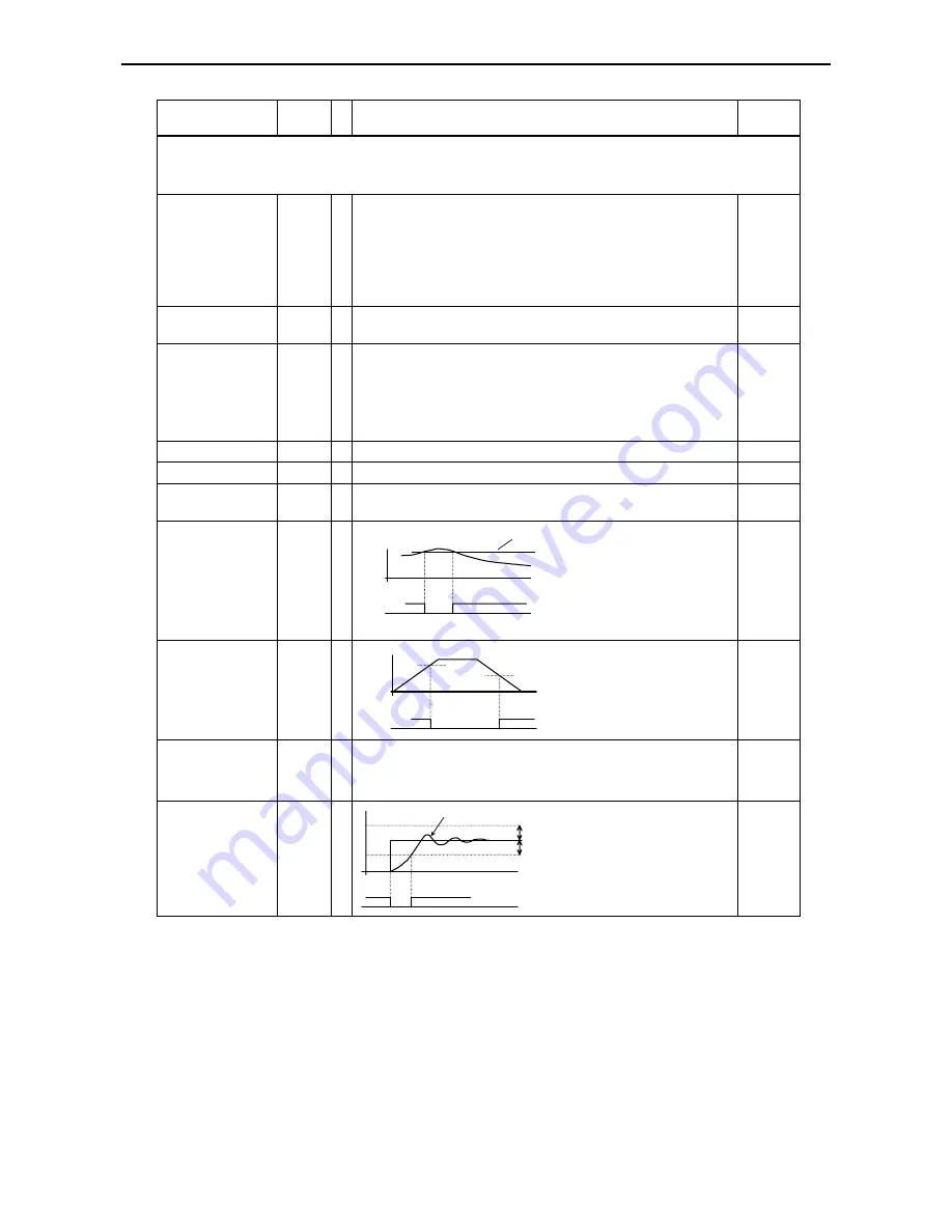
Level for overload 

signal  

C 41 

Motor

current

C 41

OL signal


Inverter 

rated 

current 


Arrival frequency 

FA2 for acceleration 

C 42 

f

C 43

FA2 signal

C 42


0.0 


Arrival frequency 

FA2 for deceleration 

C 43 

(The digital output terminal 11 or 12 configured as FA2 will remain 
activated during deceleration as long as the actual frequency is above 
the frequency entered here (also refer to the figure under 

C 42

). 

(Setting range: 0Hz–360Hz) 

0.0 


Level of PID 

deviation  

C 44 

OD signal

C 44

C 44

Actual value

Set value


3.0 


The digital output terminal 11 or 12 
configured as OD will be activated 
when the difference between the set 
value and actual value exceeds the 
value entered here (when PID control 
is activated). (Setting range: 0–100% 
of the maximum set value). 

If digital output terminals 11  
or 12 have been configured for 
output of the overload signal 
then the current value entered 
here determines when the over-
load signal will be activated. 

(Setting range: 0A–2* Inverter rated current) 

The digital output terminal 11 or 
12 configured as FA2 will be 
activated when the frequency 
entered here is exceeded during 
acceleration. 
(Setting range: 0Hz–360Hz) 

Содержание L100 IP Series

Страница 1: ...ITACHI Series Inverter Instruction Manual Single phase input 200V class Three phase input 400V class After reading this manual keep it handy for future reference Manual Number NUL100IPV6 MADE IN SLOVENIA ...

Страница 2: ......

Страница 3: ...ial Extreme care should be taken to protect against shock For these reasons the following safety guidelines should be observed Stand on an insulating pad and make it a habit to use only one hand when checking components Disconnect power before checking controllers or performing maintenance Be sure that equipment is grounded properly Wear safety glasses whenever working on an electronic controller ...

Страница 4: ...must be provided in order to avoid injury CAUTION Alarm connections may have hazardous live voltages even when the inverter is disconnected In case of removing the front cover for maintenance or inspection confirm that incoming power for alarm connections is surely disconnected CAUTION Main terminals or other hazardous terminals for any interconnection terminals for connecting the motor contact br...

Страница 5: ...installation manual D Installation For L100IP series inverters the filters described hereafter have to be used and the installation notes have to be observed If installed according to the following directions the frequency inverters comply with the following standards Emmissions EN 61800 3 EN 55011 group 1 class B Immunity EN 61800 3 industrial environments For the best possible damping of interfe...

Страница 6: ...e motor housing and carefully remove this paint if necessary 4 Very frequently interference is coupled in through installation cables This influence you can minimize Lay interfering cables separately a minimum of 0 25 m from cables susceptible to interference A particularly critical point is laying cables parallel over larger distances If two cables intersect the interference is smallest if they i...

Страница 7: ...IT TERMINAL FUNCTIONS OVERVIEW 7 1 FM TERMINAL 7 3 TERMINALS 1 5 PROGRAMMABLE DIGITAL INPUTS General notes 7 4 FW Start stop forward run 7 5 RV Start stop reverse run 7 5 CF1 CF4 Multistage speed settings 7 6 AT Analog set value using current 4 20mA 7 7 2CH Second stage acceleration deceleration 7 7 FRS Free run stop 7 8 EXT External trip 7 8 USP Prevention of restart upon power recovery 7 9 RS Re...

Страница 8: ... 1 CHAPTER 12 WIRING EXAMPLES SET VALUE SUPPLIED BY EXTERNAL POTENTIOMETER 12 1 INVERTER OPERATION USING ANALOG SET VALUE 12 2 INVERTER OPERATION USING FIXED SET VALUES 12 3 CHAPTER 13 THE OPTIONAL REMOTE OPERATORS CONNECTION OF THE REMOTE OPERATOR 13 1 THE MONITOR MODE 13 2 THE FUNCTION MODE 13 3 PROTECTIVE FUNCTIONS 13 6 DIMENSIONS OF ACCESSORIES 13 7 USING THE COPY UNIT 13 8 CHAPTER 14 SERVICE ...

Страница 9: ...h as a steel plate Wiring WARNING The inverter has to be grounded properly Otherwise there is a danger of fire WARNING Wiring work must only be carried out when the power supply is off Otherwise there is a danger of electric shock and or fire WARNING Before carrying out the wiring work the inverter has to be mounted properly Otherwise there is a danger of electric shock or injury CAUTION Make shur...

Страница 10: ...ns have to be made in order to prevent a restart after power recovery Otherwise there is a danger of injury WARNING The STOP key is effective only if the corresponding parameters have been set Otherwise there is a danger of injury WARNING If a reset is carried out following a trip condition the motor will restart if the operation command has been given Be sure to acknowledge this trip condition wi...

Страница 11: ...failure and if an operation instruction has been given then the inverter may restart operation after the power failure has ended If there is a possibibility that such an occurrence may harm humans then install an electromagnetic contactor on the primary power supply side of the inverter so that the circuit does not allow automatic restarting after the power supply has recoverd If the optional remo...

Страница 12: ...sing a short bus to the same power supply 2 A thyristor converter and an inverter are interconnected using a short bus 3 An installed power factor compensating device is connected or disconnected In the cases mentioned above we recommend installing an AC reactor of 3 voltage drop at rated current with respect to the supply voltage on the power supply side CAUTION When an EEPROM error occurs trip E...

Страница 13: ...03 HITACHI Model designation example for L100IP 007NFE 510 Applicable motor capacity example 0 75kW 1HP Inverter input specifications Frequency voltage number of phases current Inverter output specifications Frequency voltage rated current Manufacturing number date example April 2003 831079 3 298046 030300067 EAN code www hitachi ds com Hitachi Europe GmbH In the illustration below the contents of...

Страница 14: ...Chapter 2 Inspection upon unpacking 2 2 ...

Страница 15: ... names of parts Terminal cover revealed Specification label Terminal cover Digital operator Casing plastic part Casing metal part Fan inside air inlet Cable glands Grounding terminal PE Mains circuit terminals Fan cable Control terminals Serial interface Alarm terminals ...

Страница 16: ...Chapter 3 Appearance and names of parts 3 2 ...

Страница 17: ...cted Ingress of dust is not totally prevented but dust shall not penetrate in a quantity to interfere with satisfactory operation of the apparatus or to impair safety The inverter shall not be exposed to severe environmental conditions for more than 8 h test condition Protection of the equipment inside the enclosure against harmful effects due to the ingress of water indicated by the second charac...

Страница 18: ...approx 1cm Inverter Air flow The inverter must be installed vertically do not install it on the floor or horizontally Wall or mounting surface The mounting base must be a non flammable material e g metal approx 10cm The minimum clearances to the surrounding walls shown in the figure are only meant for reference A more compact installation back to back or side by side may well be possible and shoul...

Страница 19: ...ifier are not an absolute protection against direct touching CAUTION Each phase of the power supply has to be provided with a fuse Otherwise there is a danger of fire CAUTION As for motor leads earth leakage breakers and electromagnetic contactors be sure to use the ones that have the correct rating Otherwise there is a danger of fire CAUTION Make sure that the mains supply leads are reliably fixe...

Страница 20: ... figure shows the location of the control terminals The exact use of each of the control terminals is described later in this chapter The figure below contains an example for control terminal wiring Reset RS FA1 Prevention of restart USP Jogging run JG Reverse run RV Forward run FW 24VDC Common for inputs RUN Potentiometer 1k 2kOhm for frequency set value Frequency meter 24V DC max 50mA L 3 4 5 2 ...

Страница 21: ...erwise the surge voltage created when the relay goes on or off may damage the output circuit Be sure that the specified grounding is carried out Separate the inverter s grounding pole from those of other heavy electric machinery and avoid using common grounding poles when multiple inverters are employed Inverter 1 Inverter 2 Inverter 3 Grounding point Grounding point WRONG CORRECT Inverter 1 Inver...

Страница 22: ...DC power supply terminal left half of figure below and when using a separate external 24VDC power supply right half of figure below L100IP series frequency inverter L1 L L2 L3 N U V W 1 2 3 4 5 L P24 AL0 AL1 AL2 Motor Alarm terminals 1 2 3 4 5 S COM Transistor output driver YTS48 or similar 24VDC Note Note Do not short circuit the terminals P24 and L by mistake because this may lead to a malfuncti...

Страница 23: ...r model Power lines Cable diameter Signal lines 0 4 L100IP 004NFE L100IP 004NFU 1 5 mm 2 AWG 15 10 A 0 75 L100IP 007NFE L100IP 007NFU 2 5 mm2 AWG 13 16A 1 5 L100IP 015NFE L100IP 015NFU 4 0 mm2 AWG 11 25 A 200V single phase 2 2 L100IP 022NFE L100IP 022NFU 4 0 mm2 AWG 11 40 A 0 75 L100IP 007HFE L100IP 007HFU 1 5 L100IP 015HFE L100IP 015HFU 2 2 L100IP 022HFE L100IP 022HFU 1 5 mm2 AWG 15 10A 4 0 L100I...

Страница 24: ...hens motor run and so reduces torque ripple When the cable between the inverter and the motor is too long this part also forces the voltage dv dt to be limited and so protects the isolation of the motor Note Usage of an EMI filter is necessary for the European EMC directive for the Australian C TICK and others In comparison the other parts mentioned in the table above are not intended for this spe...

Страница 25: ...ws Screw Torque in Nm M2 Typ 0 20 Max 0 25 M3 Typ 0 50 Max 0 60 M3 5 Typ 0 80 Max 0 90 M4 Typ 1 20 Max 1 30 M5 Typ 2 00 Max 2 20 The next table describes the purpose of each control terminal To be continued on next page Terminal category Sym bol Purpose Initial setting Remarks 5 Reset input 4 Multistage frequency input USP function 3 Multistage frequency input use 4 20mA input 2 Reverse run 1 Thes...

Страница 26: ...nals for the following situations Signal when reaching set value or passing a configurable frequency signal during motor run overload signal PID deviation signal alarm signal Signal during motor run Outputs of open collector type for connection to a relay max 27V DC and max 50mA Digital output CM2 Common for digital outputs AL0 AL1 Fault alarm output AL2 AL0 AL1 AL2 Initial setting During normal o...

Страница 27: ...nal screws must be sufficiently tightened 9 The configurable maximum output frequency parameter must be chosen in accordance with the maximum frequency of the connected motor and machine Do not carry out any withstand voltage tests because the inverter has a surge absorber between the mains circuit terminals and the ground Test run Below an example for an inverter connection is shown For the initi...

Страница 28: ...ts to run and the the RUN lamp lights up 5 The actual frequency can be monitored using function d 01 6 You can stop the test run by pressing the STOP key CAUTION After the test run has been completed check the following items to ensure that the motor will not be damaged Was the direction of the motor run correct Was there any trip condition during acceleration or deceleration Were there any unusua...

Страница 29: ...5 can be programmed as a PTC thermistor input using C 05 The terminal L serves as common for the thermistor input AT 16 Activate input OI cur rent set value 4 20mA When the AT input is activated then the set value will be a 4 20mA current that has to be supplied at the terminals OI and L 2CH 09 2 stage acceleration deceleration Using this input the second stage acceleration and deceleration time c...

Страница 30: ...igital output is configured as FA1 then a signal is output as long as the output frequency is held constant at set value With a digital output being configured as FA2 a signal will be output as long as the actual output frequency is above the values set under C 42 and C 43 RUN 00 RUN signal The RUN signal is active as long as the motor is running OL 03 Overload signal The OL signal will be output ...

Страница 31: ...pproximately 50 Digital fre quency meter 10V f T 1 outputfrequency factor T The signal frequency equals the actual output frequency multiplied by the factor configured under b 86 3 Motor current display using analog output signal This signal is identical to the one described under 1 The width of the pulses is proportional to the actual motor current The maximum voltage of 10V is reached when the m...

Страница 32: ...ever two inputs can not be assigned to an identical function at the same time The programmable digital inputs 1 5 are factory set as normally open contacts So when a terminal s function is to be activated the digital input configured for this function has to be closed i e the input terminal must be connected to terminal P24 Likewise deactivating of an input means opening this input Alternatively t...

Страница 33: ...ntact and is subsequently configured as a normally closed contact the motor starts as soon as the reconfiguration is complete RV Start stop reverse run Terminal function When a digital input configured as RV is activated the motor starts running in the reverse direction When it is deactivated the motor stops 5 4 3 2 1 P24 RV The motor stops if both the FW and the RV inputs are activated Configurat...

Страница 34: ... 0 0 1 0 0 0 1 2 0 0 1 0 3 0 0 1 1 4 0 1 0 0 5 0 1 0 1 6 0 1 1 0 7 0 1 1 1 8 1 0 0 0 9 1 0 0 1 10 1 0 1 0 11 1 0 1 1 12 1 1 0 0 13 1 1 0 1 14 1 1 1 0 15 1 1 1 1 Note 0 Input deactivated 1 Input activated CF2 CF3 FW RV CF1 Frequ 1 Frequ 2 Frequ 3 Frequ 5 Frequ 6 Frequ 7 Frequ 4 Frequ 0 Configuration A 21 A 35 C 01 C 05 F 01 Configure one or more of the digital inputs 1 5 as CF1 CF4 input by enterin...

Страница 35: ...alues present on terminal O resp OI are added 2CH Second stage acceleration deceleration Terminal function When a digital input configured as 2CH is activated then the motor is accelerated or decelerated using the 2 stage acceleration or deceleration time When the 2CH input is deactivated again the inverter is switched back to acceleration respectively deceleration time 1 5 4 3 2 1 P24 2CH FW Term...

Страница 36: ...r speed should take place after a certain waiting time parameter 01 The waiting time can be set using b 03 2 Configure one of the digital inputs 1 5 as FRS input by entering the parameter 11 under C 01 C 05 EXT External trip Terminal function When a digital input configured as EXT can be used as an input for e g thermo contacts is activated then the inverter enters the trip state with an error ind...

Страница 37: ...s alarm output Running command 5 4 3 2 1 P24 USP FW Configuration C 01 C 05 Configure one of the digital inputs 1 5 as USP input by entering the parameter 13 under C 01 C 05 WARNING In case of an USP condition indicated by trip E 13 resetting the trip while the running command activated FW or RV input is still active will cause the motor to restart immediately Remarks When a running command is iss...

Страница 38: ... Consequentely be sure to acknowledge the trip only after having made sure that the running command is not currently active Otherwise there is a danger of injury to personnell Remarks The STOP key on the digital operator functions as RESET key when a trip condition has occurred So in this case it can be used for resetting the inverter instead of the RS input If the RS input is held active for more...

Страница 39: ...d Please remember not to use a too high frequency since the frequency is directly sent to the motor without an acceleration ramp which may lead to a trip You should set a frequency that is less than 5Hz 2 Since in jogging mode the running command is issued using inputs FW or RV you have to set A 02 to 01 3 A 39 determines the way the motor decelerates The parameters 00 free run stop this is the de...

Страница 40: ...nfigured as PTC without a thermistor being connected to input 5 trip E 35 will be displayed The PTC input is always a normally open contact and can not be configured a normally closed contact SFT Software lock Terminal function When a digital input configured as SFT is activated then the configured parameters can not be overwritten by mistake 5 4 3 2 1 P24 SFT FW Configuration b 31 C 01 C 05 1 Fir...

Страница 41: ... CM2 24V The programming of the desired terminal function for each of the two digital outputs 11 and 12 is carried out using C 21 and C 22 i e C 21 is used to set the function of digital output 11 and C 22 is used to set the function of digital output 12 The programmable digital outputs are factory preconfigured as normally closed contacts So if the configured function of an output terminal is to ...

Страница 42: ... C 21 C 22 C 42 C 43 1 If a programmable digital output is to be configured with FA2 output function first of all a frequency has to be set using C 42 at which the FA2 signal is to be activated during acceleration Next a frequency has to be set at which the FA2 signal is to be deactivated again this is done using C 43 2 Then configure under C 21 or C 22 one of the digital outputs 11 or 12 as FA1 o...

Страница 43: ... of the digital outputs 11 or 12 as OL output by entering the parameter 03 under C 21 or C 22 OD PID deviation Terminal function A digital output configured as OL is activated when a user definable PID deviation threshold current value set value is exceeded The OD output remains activated as long as this deviation is greater than the predetermined level Signal active Current value Threshold C 44 O...

Страница 44: ... is switched on until the AL output is closed deactivated and thus a trip condition is indicated for a short time The programmable digital outputs including an output configured as AL are of open collector type and so have different electrical characteristics compared with the alarm relay output terminals AL0 AL1 and AL2 Especially the maximum voltage and current load ratings are much more restric...

Страница 45: ...N C contact C 33 01 N O contact C 33 00 Configuration C 33 Refer to the above table to configure the contacts AL0 AL1 and AL0 AL2 as normally closed or normally open contacts using C 33 Remarks After a trip has occurred the trip message displayed is conserved even when the power to the inverter is switched off For this reason this trip message can be displayed again when the inverter is switched o...

Страница 46: ...Chapter 7 Control circuit terminal functions 7 18 ...

Страница 47: ...s key is available PRG Lamp This lamp is on while a parameter is being set RUN Lamp This lamp is on when the inverter is running or the run command is active Monitor LED Display This display shows frequency motor current DC voltage motor direction and parameters STOP Reset Key This key is used for stopping the motor or resetting errors or trips When the keypad is selected this key is functional no...

Страница 48: ...4 deter mines forward or reverse run STOP key This key stops the L100 inverter When a trip occurs this key becomes the RESET key Setting parameters for extended functions example for extended functions of group A When an extended function is to be used select the extended function group from or by using the two keys and so as to enter the extended function mode FUNC FUNC FUNC STR FUNC Extended fun...

Страница 49: ... 0 5Hz 360Hz The Hz lamp on the digital operator lights up Motor current monitor A d 02 Displays motor current 0 01A 999 9A The A lamp on the digital operator lights up Running direction monitor d 03 Display F for forward run r for reverse run 0 for stop PID feedback monitor d 04 Only when PID control is activated The factor is set using A 75 0 01 through 99 99 standard setting 1 0 Input terminals...

Страница 50: ...h 3000 10 0 Motor direction F 04 N After pressing the RUN key the motor starts in forward running mode parameter 00 or in reverse running mode parameter 01 00 Extended functions of group A Group A comprises a variety of functions among them functions for adjusting the frequency set value functions for setting up multistage speed settings as well as functions for configuring parameters for a DC bra...

Страница 51: ...arameter setting range Standard setting Multistage frequency settings and jogging mode Up to 15 multistage frequency settings can be selected using the digital inputs configured as CF1 through CF4 Alternatively to setting the multistage frequencies under functions A 21 through A 35 they can be set using function F 01 Jogging mode can be used to set up a machine manually and is activated using a di...

Страница 52: ...th as short a braking torque and braking time as possible DC brake active not active A 51 N 00 DC brake is not used not 01 DC brake is used active 00 DC brake frequency A 52 N The DC brake will be activated as soon as the actual output frequency falls below the frequency entered here Setting range 0 5Hz 10Hz 0 5 DC brake waiting time A 53 N When the frequency set under A 52 is reached the motor ru...

Страница 53: ...ow or throughput of 0 to 30l h The PID control output is limited to a lower limit of 0 Hz or the frequency set under A 62 and to the frequency set under A 04 or A 61 respectively as an upper limit This ensures that the motor running direction will not be reversed when a negative deviation is present In order to optimize the PID control s behaviour it is advisable to keep acceleration and decelerat...

Страница 54: ...Although these gains can be set independently of each other there are interactions between them When the P gain kp is changed the effective I gain changes TN also Only when kp 1 the effective I gain TN is equal to the I gain that had been entered TN When kp is not equal to 1 TN can be calculated as follows TN TN kp refer to the figure on the right PID block diagram P A 72 I A 73 D A 74 F 01 Monito...

Страница 55: ... to be entered under A 45 FE models 230 400 FU models 230 460 Function Display Function description parameter setting range Standard setting Time ramps f A 95 0 t 2CH or A 95 Accel 1 Accel 2 2 Acceleration time A 92 Y Setting range 0 1s 999 9s Resolution 0 1s 1000s 3000s Resolution 1s 15 0 2 Deceleration time A 93 Y Setting range 0 1s 999 9s Resolution 0 1s 1000s 3000s Resolution 1s 15 0 Method to...

Страница 56: ... motor s current speed and the motor is decelerated using the configured deceleration time Afterwards the corresponding trip will be displayed 00 Allowable under voltage failure time b 02 N Here the time is entered during which the undervoltage condition is met while the corresponding trip E 09 is not being displayed Setting range 0 3s 25s 1 0 Waiting time until retry b 03 N Here the time is enter...

Страница 57: ...e lock initiated by input SFT all functions locked 01 Software lock initiated by input SFT function F 01 still usable 02 Software lock all functions locked 03 Software lock function F 01 still usable 01 Magnetizing current b 32 N This function will be available from July 1998 The date on the name plate must read 9807 or later Magnetizing current can be configured when smaller motors are used or wh...

Страница 58: ...ean version Enter 00 or 01 under b 84 On the digital operator press the two arrow keys and the FUNC key simultaneously While holding down the keys mentioned above press the STOP key shortly and wait about 3 seconds for the LED display to show the message d 00 in a blinking manner Now release the keys again The initialization has now been completed Set the correct carrier frequency see back of the ...

Страница 59: ...stop forward run 01 RV start stop reverse run 02 CF1 1 multistage frequency input 03 CF2 2 multistage frequency input 04 CF3 3 multistage frequency input 05 CF4 4 multistage frequency input 06 JG jogging run 09 2CH 2 acceleration deceleration 11 FRS free run stop 12 EXT external trip 13 USP restart prevention function 15 SFT software lock 16 AT use input OI 18 RS reset 19 PTC thermistor input only...

Страница 60: ...y closed contact 01 Digital output 12 type C 32 N Refer to C 31 for possible parameters 01 Type of alarm relay output C 33 N Refer to C 31 for possible parameters 01 Level for overload signal C 41 N Motor current C 41 OL signal Inverter rated current Arrival frequency FA2 for acceleration C 42 N f C 43 FA2 signal C 42 0 0 Arrival frequency FA2 for deceleration C 43 N The digital output terminal 11...

Страница 61: ...may also cause motor heating and low torque The inverter is shut off when the DC bus voltage goes below a certain level E009 CPU error Malfunction or abnormality of the CPU The inverter is shut off E011 E022 External trip A trip signal from external equipment shuts off the inverter It is necessary to assign the external trip to an intelligent terminal E012 USP error Indicates an error when power i...

Страница 62: ...ettings have been selected and the inverter currently is in its initializing phase refer to functions b 84 and b 85 The parameters for the European market EU are loaded For non European inverter models there are versions for North America USA and Japan JP The trip history register is being initialized The copy unit is carrying out a copy operation No data available this may be displayed under func...

Страница 63: ...n selected Correct the A 01 parameter setting if necessary Correct the A 02 parameter setting if necessary No voltage can be measured at outputs U V and W Is the motor blocked or is the motor load too high Reduce the load that the motor drives Operate the motor without any load for testing purposes The motor won t start An optional remote operator is used Are the dip switches set correctly Check i...

Страница 64: ...verter the power supply was left in the on state for only less than 6 seconds Copy the parameter settings once more and then keep the power supply turned on for more than 6 seconds The motor won t start or stop and also no set value can be entered Have the functions A 01 and A 02 been configured correctly Check if the settings made under A 01 and A 02 are correct Has the software lock function bee...

Страница 65: ...ance 250 Ohm Potentiometer 1k 2k Ohm 1W Dig operator Via keys RUN for start and STOP RESET for stop Default setting forward run Forward Reverse run Start Stop Ext signals Intelligent input terminals configurable as FW and RV Intelligent input terminals programmable as FW Forward run start stop RV Reverse run start stop CF1 CF4 Multistage speed JG Jogging command AT Analog current input selection 2...

Страница 66: ... 2k Ohm 1W Dig operator Via keys RUN for start and STOP RESET for stop Default setting forward run Forward Reverse run Start Stop Ext signals Intelligent input terminals configurable as FW and RV Intelligent input terminals programmable as FW Forward run start stop RV Reverse run start stop CF1 CF4 Multistage speed JG Jogging command AT Analog current input selection 2CH 2 Accel decel time FRS Fre...

Страница 67: ... 60 Hz Fuses L100IP series inverter L1 L L2 L3 N U V W 1 2 3 4 5 L P24 H O OI L FM AL0 AL1 AL2 11 CM2 12 Motor Ground Alarm signal relay output C Thermistor Frequency monitor Set value input 4 20 mA Analog set value 0 10V Pot 1k 2k Ohm Power supply Running command Output frequency 2 s The common potential depends on the terminals used Terminals Common potential 1 2 3 4 5 P24 FM H O OI L 11 12 CM2 ...

Страница 68: ...nical specifications 11 4 External dimensions of L100IP series inverters L100IP 004NFE NFU L100IP 007NFE NFU L100IP 015NFE NFU L100IP 022NFE NFU L100IP 007HFE HFU L100IP 015HFE HFU L100IP 022HFE HFU L100IP 040HFE HFU ...

Страница 69: ...Chapter 11 Technical specifications 11 5 L100IP 055HFE HFU L100IP 075HFE HFU Hz A RUN 1 2 PRG Detail of dimension and fixing point of 055 and 075 are matters to be changed when they are released ...

Страница 70: ...P 007NFE NFU L100IP 015NFE NFU L100IP 022NFE NFU L100IP 007HFE HFU L100IP 015HFE HFU L100IP 022HFE HFU L100IP 040HFE HFU L100IP 055HFE HFU L100IP 075HFE HFU 205 O7 6 188 6 490 477 7 168 185 477 490 7 6 6 O7 Detail of dimension and fixing point of 055 and 075 are matters to be changed when they are released ...

Страница 71: ...on digital input 2 C 23 00 Monitoring of output frequency analog using the meter connected to terminals L and FM b 81 80 Adjustment of the frequency meter connected to terminals L and FM Function description The inverter can now be started via input 1 forward run or input 2 reverse run If the inputs RV and FW are both closed the inverter is stopped By adjusting the external potentiometer the desir...

Страница 72: ...puts 1 and 2 are used exactly the way as described in the previous example Digital input 3 configured as AT can be used to switch from voltage set value 0 10V to current set value 4 20mA If none of the digital inputs has been configured as AT then the voltage set value present on terminal O and the current set value present on terminal OI will be added Instead of a fixed wiring or one that uses a ...

Страница 73: ...ency 3 Here the fixed frequency is entered that will be output when CF1 and CF2 are both active Function description The inputs 1 and 2 are used exactly the way as described in the previous example When one or both of the multistage frequency inputs CF1 and CF2 are activated then the current active frequency output is superseded by the fixed frequency set by the combination of inputs CF1 and CF2 C...

Страница 74: ......

Страница 75: ...n configured using L100IP series inverters can now be copied to other inverters using the copy unit DRW 0A2 The old model DRW 0A can not be used for this purpose When inverters are operated with a remote operator connected the following items must be noted The remote operator s cable must not be attached or removed during operation i e if the power supply to the inverter is switched on The digital...

Страница 76: ...z01 0 01 0 1 0 0 1 99 9 Y Display only d 07 b 86 Motor current Im 0 0A 0 0 Display only Displays current in A left and of rated current right d 02 Magnetizing current I0 A Rated cur rent 0 58 0 32A N b 32 Manual boost V Boost Code 11 11 00 99 Y A 42 Manual boost fre quency adjustment V Boost F 10 0 10 0 0 50 Y A 43 Boost method V Boost Mode 0 0 0 1 N A 41 Output voltage gain V Gain 100 100 50 100 ...

Страница 77: ...1 Deceleration time DEC1 0010 0s 10 0s 10 0s 0 1 3000 F 03 2 Deceleration time DEC2 0015 0s 15 0s 15 0s 0 1 3000 A 93 Decel 1 Decel 2 switchover frequency DEC CHFr 000 0Hz 0 0Hz 0 0Hz 0 360 A 96 F 07 Deceleration characteristic DEC LINE L L L L S A 98 F 10 Operation method after FRS cancelled RUN FRS ZST ZST ZST fST ZST b 88 Multistage frequency setting 1 SPD 1 005 0Hz 0Hz 0Hz 0 360 A 21 Multistag...

Страница 78: ...uency end point bias IN EX E 100 100 100 0 100 A 14 External frequency start pattern IN LEVEL 0Hz 0Hz 0Hz 0Hz EXS A 15 F 31 Analog input filter time constant IN F SAMP 8 8 8 1 8 A 16 Arrival frequency FA2 for acceleration ARV ACC 000 0Hz 0Hz 0Hz 0 360 C 42 F 32 Arrival frequency FA2 for deceleration ARV DEC 000 0Hz 0Hz 0Hz 0 360 C 43 Level for overload signal OV Load 16 50A Rated current Rated cur...

Страница 79: ...5 Motor direction INIT DOPE FWD FWD FWD FWD REV F 04 F 38 Initializing mode INIT MODE TRP TRP TRP TRP DATA b 84 PID control active not active PID SW OFF OFF OFF OFF ON A 71 P proportional gain of PID control PID P 1 0 1 0 1 0 0 2 5 A 72 I integral gain of PID control PID I 001 0 1 0 1 0 0 150 A 73 D differential gain of PID control PID D 000 0 0 0 0 0 0 100 A 74 Scale conversion of PID control PID...

Страница 80: ...Undervoltage protection A decrease of DC bus voltage may result in improper function of the control unit It may also cause motor heating and low torque The inverter is shut off when the DC bus voltage goes below a certain level Under V CPU1 CPU error Malfunction or abnormality of the CPU The inverter is shut off CPU2 External trip A trip signal from external equipment shuts off the inverter It is ...

Страница 81: ... tensive cable The cables ICL J 1 and ICL J 3 are designed for connection to the remote operator OPE J and the cables ICA 1L J and ICA 3L J are used for connection of a remote operator or copy unit to L100IP and J100 J300 series inverters The remote operator OPE J can only be used for displaying data when connected to an L100IP series inverter also refer to the description of function b 89 in chap...

Страница 82: ...nsferred to three other inverters B C and D No Action Key s Result 1 Connect the cable and press the REMT key Now change some inverter parameters using the copy unit MON FUN STR Arrow keys Inverter A Copy unit Copy data H z A R U N 1 2 P R G 2 to 6 Read out the data of inverter A the data will then be stored into the copy unit Now proceed as described in the previous example under items 2 through ...

Страница 83: ...shall be under normal inverter installation and handling conditions twelve 12 months from the date of installation and eighteen 18 months from the date of production This warranty will not cover the following cases even when the date the problem arises lies within the warranty period In these cases the costs for service that the purchaser has ordered will be charged to the purchaser himself Invert...

Страница 84: ......

Страница 85: ...tandard setting S e t v a l u e A 01 Frequency set value source 00 NOT IN USE 01 Input O OI 02 Functions F 01 A 20 01 A 02 Run command source 01 Input FW RV 02 RUN key 01 A 03 Base frequency A 04 Maximum frequency FE 50 FU 60 A 11 External frequency start point 0 A 12 External frequency end point 0 A 13 External frequency start point bias in 0 A 14 External frequency end point bias in 100 A 15 Ext...

Страница 86: ...y lower limit 0 0 A 63 1 Jump frequency 0 0 A 65 2 Jump frequency 0 0 A 67 3 Jump frequency 0 0 A 64 1 Jump frequency width 0 5 A 66 2 Jump frequency width 0 5 A 68 3 Jump frequency width 0 5 A 71 PID control active 00 No 01 Yes 00 A 72 P gain of PID control 1 0 A 73 I gain of PID control 1 0 A 74 D gain of PID control 0 0 A 75 Scale conversion of PID control 1 00 A 76 Feedback signal location of ...

Страница 87: ...01 initiated by input SFT function F 01 usable 02 without input SFT all functions locked 03 without input SFT function F 01 usable 01 b 32 Magnetizing current This function will be available from July 1998 The date on the name plate must read 9807 or later Rated current 0 58 b 81 Analog meter adjustment on FM terminal 80 b 82 Start frequency 0 5 b 83 Carrier frequency in kHz 2 0 or 5 0 b 84 Initia...

Страница 88: ...1 n c 00 C 12 Type of digital input 2 for params refer to C 11 00 C 13 Type of digital input 3 for params refer to C 11 00 C 14 Type of digital input 4 for params refer to C 11 FE 00 FU 01 C 15 Type of digital input 5 for params refer to C 11 00 C 21 Function of digital output 11 00 RUN signal 01 FA1 frequency arrival 02 FA2 frequency exceeded 03 OL overload 04 OD PID de viation exceeded 05 AL ala...

Страница 89: ...stage frequency setting 3S000 0 0 0Hz 0 0Hz 4 Multistage frequency setting 4S000 0 0 0Hz 0 0Hz 5 Multistage frequency setting 5S000 0 0 0Hz 0 0Hz 6 Multistage frequency setting 6S000 0 0 0Hz 0 0Hz 7 Multistage frequency setting 7S000 0 0 0Hz 0 0Hz 8 Multistage frequency setting 8S000 0 0 0Hz 0 0Hz 9 Multistage frequency setting 9S000 0 0 0Hz 0 0Hz 10 Multistage frequency setting 10S000 0 0 0Hz 0 0...

Страница 90: ... V ERR1 31 0Hz ERR1 12 5A ERR1 787 0Vdc Trip history register Last trip ERR1 RUN 000001H Display only no params can be entered Trip counter ERROR COUNT 25 Display only no params can be entered ERR2 ERR2 OC Accel ERR2 5 0Hz ERR2 20 1A ERR2 560 0Vdc Trip history register Last trip but one ERR2 RUN 000002H Display only no params can be entered ERR3 ERR3 EXTERNAL ERR3 5 0Hz ERR3 20 1A ERR3 560 0Vdc Tr...

Страница 91: ...equency setting SPD 4 005 0Hz 0Hz 0Hz 5 Multistage frequency setting SPD 5 005 0Hz 0Hz 0Hz 6 Multistage frequency setting SPD 6 005 0Hz 0Hz 0Hz 7 Multistage frequency setting SPD 7 005 0Hz 0Hz 0Hz 8 Multistage frequency setting SPD 8 005 0Hz 0Hz 0Hz 9 Multistage frequency setting SPD 9 005 0Hz 0Hz 0Hz 10 Multistage frequency setting SPD10 005 0Hz 0Hz 0Hz 11 Multistage frequency setting SPD11 005 0...

Страница 92: ...t F 33 Level of PID deviation OV PID 003 0 3 3 Function of digital input 1 IN TM 1 FW FW FW Function of digital input 2 IN TM 2 RV RV RV Function of digital input 3 IN TM 3 CF1 CF1 AT Function of digital input 4 IN TM 4 CF2 CF2 USP Function of digital input 5 IN TM 5 RS RS RS Type of digital input 1 IN TM O C 1 NO NO NO Type of digital input 2 IN TM O C 2 NO NO NO Type of digital input 3 IN TM O C...

Страница 93: ...ion arrow keys on the digital operator 2 While holding down the mentioned keys press the STOP key for a short time and wait for about 3 seconds until the blinking message d 00 is shown on the display 3 Now release all keys again The initializing phase that now begins will be complete as soon as the display 00 appears output frequency display 4 Set the carrier frequency b 83 to acceptable value max...

Страница 94: ...on t open the front case Otherwise there is a danger of electric shock Once a month or more frequent depending on pollution condition check if the fan is freely rotating check that there is no dust on fan If any clean it away pull the cables to check whether the glands firmly hold them tighten the glands if necessary open the terminal cover and check whether there is any dust or humidity if any pl...

Отзывы: