vi
FIGURES
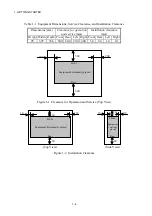
Figure 1-1 Clearance for Operation and Service (Top View) .............................................
1-4
Figure 1-2 Installation Clearance ........................................................................................
1-4
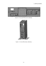
Figure 1-3 Horizontal Placement on Desktop .....................................................................
1-5
Figure 1-4 Vertical Placement on Desktop ..........................................................................
1-5
Figure 1-5 Hardware Connection ........................................................................................
1-8
Figure 2-1 Elements in Operator Access Areas—Front View ..............................................
2-2
Figure 2-2 Elements in Operator Access Areas—Rear View on HJ-2035 ............................
2-3
Figure 2-3 Elements in Operator Access Areas—Rear View on HJ-2030 ............................
2-3
Figure 2-4 Internal Construction—Internal View on D Model of HJ-2035 ........................
2-4
Figure 2-5 Internal Construction—Internal View on A Model of HJ-2035 ........................
2-5
Figure 2-6 Internal Construction—Internal View on A Model of HJ-2030 ........................
2-5
Figure 3-1 Front View of DVD Drive in the Equipment ....................................................
3-5
Figure 5-1 Extended Board Types and Mounting Positions on HJ-2035 ...............................
5-8
Figure 5-2 Extended Board Types and Mounting Positions on HJ-2030 ...............................
5-9
Figure 5-3 Unmounting the Cover of the Equipment .......................................................... 5-10
Figure 5-4 Removing the Screw Fixing the Riser Unit on HJ-2035 ................................... 5-11
Figure 5-5 Detaching the Riser Unit on HJ-2035 ................................................................ 5-11
Figure 5-6 Reattaching the Riser Unit on HJ-2035 ............................................................. 5-12
Figure 5-7 Detaching the Stopping Panel from the Target Slot on HJ-2035 ........................... 5-13
Figure 5-8 Inserting an Extended Board on HJ-2035 .......................................................... 5-14
Figure 5-9 Detaching the Low-profile Bracket on HJ-2030 ................................................ 5-16
Figure 5-10 Detaching the Stopping Panel from the Target Slot on HJ-2030 ...................... 5-16
Figure 5-11 Inserting an Extended Board on HJ-2030 .......................................................... 5-17
Figure 5-12 Inserting Main Memory ..................................................................................... 5-20
Figure 5-13 Detaching/Attaching HDD on D or A Model While Main Power Is Off .......... 5-24
Figure 5-14 Detaching/Attaching Vertical Stand .................................................................. 5-25
Figure 5-15 Replacing Lithium Battery ................................................................................. 5-27
Figure 5-16 Removing JP Socket .......................................................................................... 5-29
Figure 9-1 HDD Status Lamps ............................................................................................
9-3
Figure 10-1 Alarm Lamp ....................................................................................................... 10-4
Содержание HF-W2000 30
Страница 1: ...WIN 62 0060 08 ...
Страница 2: ...WIN 62 0060 08 ...
Страница 21: ...This Page Intentionally Left Blank ...
Страница 29: ...This Page Intentionally Left Blank ...
Страница 34: ...1 GETTING STARTED 1 5 Figure 1 3 Horizontal Placement on Desktop Figure 1 4 Vertical Placement on Desktop ...
Страница 125: ...This Page Intentionally Left Blank ...
Страница 165: ...7 MAINTENANCE ACTIONS 7 32 MEMO ...
Страница 189: ...9 RAID1 9 16 MEMO ...
Страница 227: ...10 SOFTWARE RAID1 10 38 MEMO ...


