124
06-1491-00-12.fm
Attachments and Options
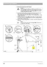
Continued – Mounting the sweeping unit (3-brush system)
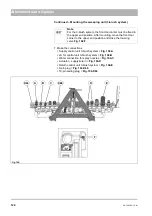
7. Make the connections.
•
Supply control unit 3-brush system =
Fig. 104-A
•
LS for control unit 3-brush system =
Fig. 104-B
•
Water connection for spray nozzles =
Fig. 104-C
•
Actuator – supply/return =
Fig. 104-D
•
Return control unit 3-brush system =
Fig. 104-E
•
9-pin plug =
Fig. 104-X66
•
19-pin coding plug =
Fig. 104-X63
Note
For the 3-brush system, the front tool carrier must be fixed in
the upper end position. After mounting, move the front tool
carrier to the upper end position and close the lowering
valve
Fig. 104-F
.
Fig. 104:
D
X63
C
E
A
B
X66
F
Содержание Citymaster 1600
Страница 22: ...22 01 1491 00 12 fm Safety Instructions G A B D E F Fig 3 C F C E C D G A B A...
Страница 26: ...26 02 1491 00 11 fm Operation Fig 5 25 23 16 18 17 19 22 21 20 24 26 27...
Страница 28: ...28 02 1491 00 11 fm Operation Fig 6 28 42 44 41 43 46 47 37 36 38 39 40 35 41 48 49 34 30 32 29 33 31 45...
Страница 30: ...30 02 1491 00 11 fm Operation Fig 7 62 63 61 67 55 50 51 54 53 52 58 57 59 60 65 64 66 68 56...
Страница 32: ...32 02 1491 00 11 fm Operation Fig 8 75 69 78 73 72 79 80 81 82 83 74 77 70 71 76 84...
Страница 85: ...04 1491 00 11 fm 85 Technical Data 4 Technical Data Fig 80 3830 1600 941 1210 975 1964...
Страница 146: ...146 06 1491 00 12 fm Attachments and Options 6 1 5 Technical data Fig 144 2215 4510 1580 2250...
Страница 220: ...220 06 1491 00 12 fm Attachments and Options...


